Peerless-AV WL-ESA763PU-200 - Installation User Manual
Page 9
9 of 25
ISSUED: 08-24-12 SHEET #: 180-9034-2 10-30-12
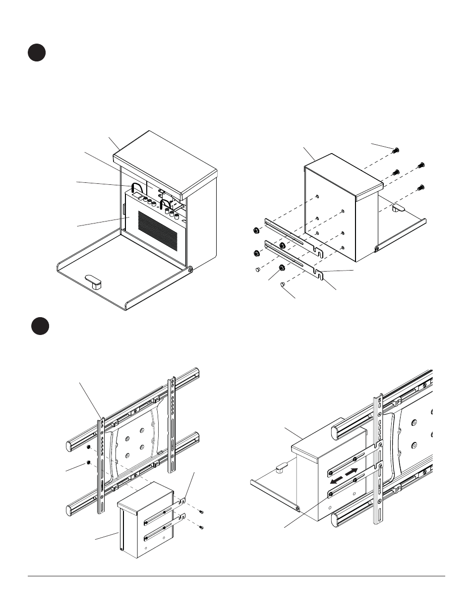
To install the enclosure to the universal adapter bracket, continue to step 4.
To install the enclosure to a wall, skip to step 7.
Open the wireless receiver enclosure (N) and unplug the wireless receiver power cord from the wireless receiver.
Remove the wireless receiver and sub panel assembly as shown in fi g. 4.1. Loosely attach the small enclosure
mounting brackets (S) to the wireless receiver enclosure (N) with two 1/4-20 x 1/2 socket head screws (Q) and two
1/4-20 nuts (R) as shown in fi g. 4.2. NOTE: The enclosure mounting bracket can be installed with the inside notch
facing downward if additional side to side adjustment is needed. Position and tighten the four 1/4-20 x 1/2 socket
head screws (Q) using 4mm allen wrench (L). Press in two plastic plugs (U) into holes shown in fi gure 4.2.
Attach the mounting brackets (S), open end of notch facing downward, to the left display bracket with two
1/4-20 x 1/2 socket head screws (Q) and two 1/4-20 nuts (R) as shown in fi g. 5.1.
Adjust the position of the enclosure (N) to your desired location as shown in fi g. 5.2 Once in position, tighten the
four 1/4-20 x 1/2 socket head screws (Q) using 4mm allen wrench (L).
4
5
Enclosure Installation
fi g. 4.1
fi g. 5.1
fi g. 5.2
fi g. 4.2
Q
S
N
N
N
R
N
S
U
Q
R
WIRELESS
RECEIVER
SUB PANEL
ASSEMBLY
WIRELESS
RECEIVER
POWER CORD
DISPLAY
BRACKET
INSIDE NOTCH