Typical operating circuit – Rainbow Electronics MAX7439 User Manual
Page 8
MAX7438/MAX7439
Microprocessor Control of High-Frequency
Boost and Bypass
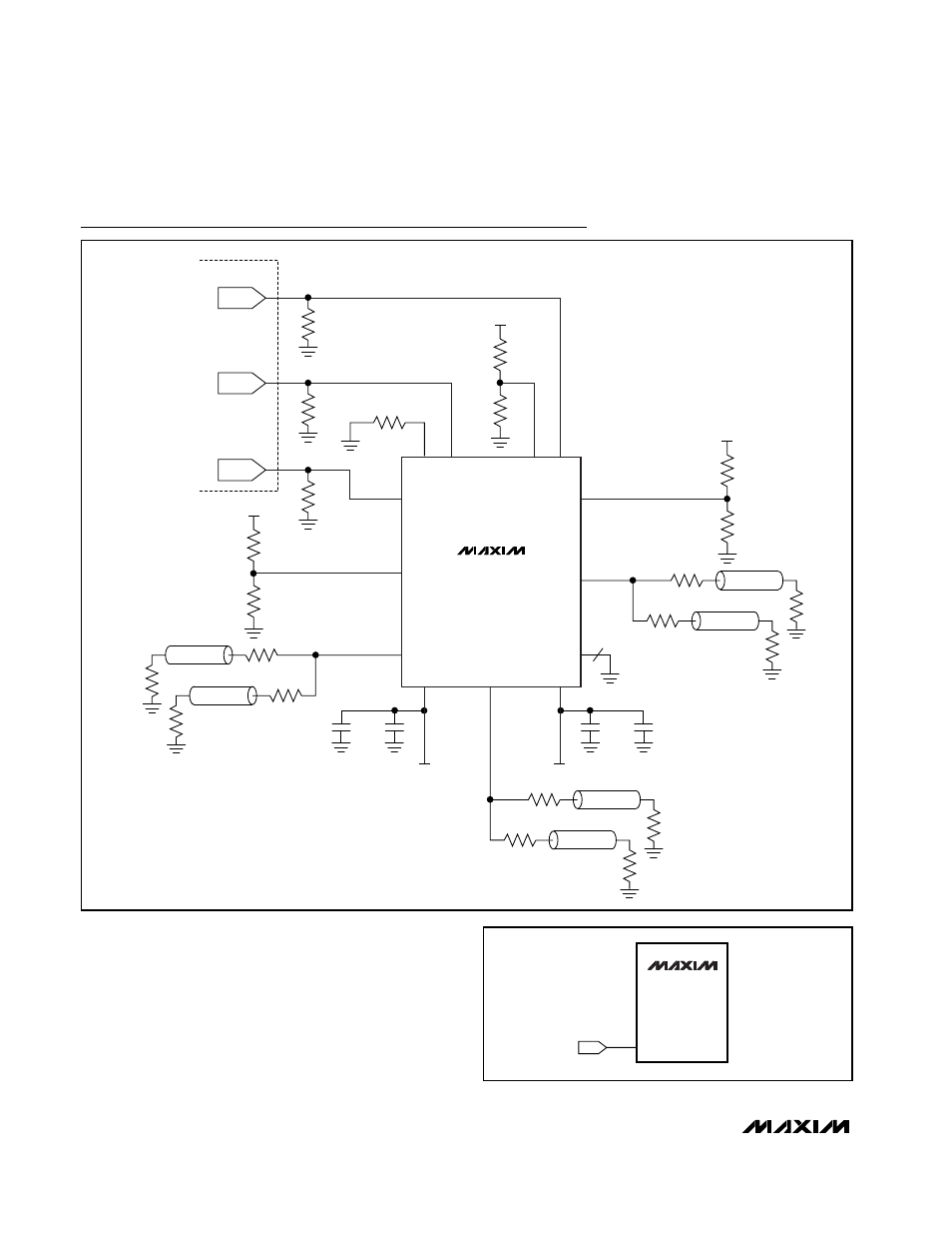
Use a DAC output to control the bypass and high-fre-
quency boost levels on each channel (see Figure 2).
Set the DAC output voltage to the corresponding
bypass or boost levels desired (see Table 1).
Triple-Channel Video Reconstruction Filters with
Back-Porch Clamp to GND
8
_______________________________________________________________________________________
OUT3
HFB3
EXT
IN2
HFB2
IN3
GND
IN1
HFB1
OUT1
MAX7438
MAX7439
DAC2
ENCODER
DAC3
V
CC
OUT2
V
SS
0.1
µF
1
µF
V
SS
= -5V
0.1
µF
1
µF
V
CC
= +5V
V
CC
R
HFB2-1
R
HFB2-2
10k
Ω
R
T
R
T
R
T
V
CC
R
HFB1-1
R
HFB1-2
DAC1
8
V
CC
R
HFB3-1
R
HFB3-2
Z
0
= 75
Ω
75
Ω
75
Ω
Z
0
= 75
Ω
75
Ω
75
Ω
Z
0
= 75
Ω
75
Ω
75
Ω
Z
0
= 75
Ω
75
Ω
75
Ω
Z
0
= 75
Ω
75
Ω
75
Ω
Z
0
= 75
Ω
75
Ω
75
Ω
Typical Operating Circuit
HFB_
MAX7438
MAX7439
DAC
Figure 2. DAC Control of High-Frequency Boost and Bypass