Installation guide, E8950 – Veris Industries E8950 Install User Manual
Page 26
TM
E8950
INSTALLATION GUIDE
ZL0105-0B
PAGE 26
©2013 Veris Industries USA 800.354.8556 or +1.503.598.4564 / [email protected]
02131
Alta Labs, Enercept, Enspector, Hawkeye, Trustat, Aerospond, Veris, and the Veris ‘V’ logo are trademarks or registered trademarks of Veris Industries, L.L.C. in the USA and/or other countries.
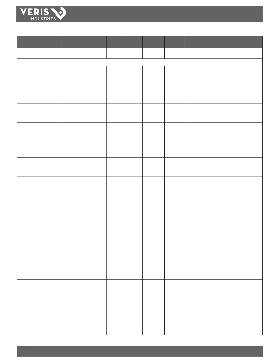
Data Variable
Description
BACnet
Object
Units
COV_
Increment
Modbus
Address
Comments
Baud rate as conf by DIP
switches
integer (2400; 4800; 9600;
19200)
AI55
n/a
0
69
Analog_Value objects: (can be written as well as read)
Reset Min/Max/Avg Real Power
Write Zero to Reset Min/Max/
Avg kW
AV1
n/a
0
28
Returns random values if read.
Reset Energy Consumption
Write Zero to Reset kWh
Accumulator
AV2
n/a
0
1
Returns random values if read.
CT Scale
Amp rating of CT used (integer)
AV3
Amps
0
30
Sets the size of the external 5-Amp CTs used. Range is 1 to
5999. E.g. for 10A:5A CTs, set register to 10; for 4000A:5A
CTs, set register to 4000.
Over Voltage (AV6) Alarm
Threshold
Alarm if L-L Voltage>threshold
> 10 sec
AV4
Volts
0
31
Occurs if the average L-L voltage (AI6) is greater than
this threshold for at least 10 seconds. Units are absolute
voltage (using integer multiplier). Range = 0 to 65535;
Default = 65535
Under Voltage (AV6) Alarm
Threshold
Alarm if L-L Voltage (ever) AV5 Volts 0 32 Occurs if the average L-L voltage (AI6) is less than this threshold at any time. Units are absolute voltage (using integer multiplier). Range = 0 to 65535; Default = 0 Over Current (AV8) Alarm Threshold Alarm if Avg Current>threshold (ever) AV6 Amps 0 33 Occurs if the average current (AI8) is greater than this threshold at any time. Units are absolute current (usinginteger multiplier). Range = 0 to 65535; Default = 65535 Under Current (AV8) Alarm Threshold Alarm if Avg Current (ever) AV7 Amps 0 34 Occurs if the average current (AI8) is less than this threshold at any time. Units are absolute current (usinginteger multiplier). Range = 0 to 65535; Default = 0 Over kVA (AV5) Alarm Threshold Alarm if kVA>threshold (ever) AV8 kVA 0 35 Occurs if the total apparent power (AI5) is greater than this threshold at any time. Units are absolute kVA (using integer multiplier). Range = 0 to 65535; Default = 65535 Under kVA (AV5) Alarm Threshold Alarm if kVA AV9 kVA 0 36 Occurs if the total apparent power (AI5) is less than this threshold at any time. Units are absolute kVA (using integer multiplier). Range = 0 to 65535; Default = 0 Meter Alarm Status (Latching) bitmap of 8 alarms - bits 9-15 are all 0 AV10 n/a 0 37 Holds the state of the meter alarm latches. These alarms are latching and must be cleared by the user. To reset any alarm, read the register and then write the register with the desired alarm bit cleared. Writing a 1 to any bit has no effect. bit 0 = over current Phase Loss Threshold Integer % of other phases AV11 Percent 0 38 Phase Loss Threshold (0 to 100%, default = 65535): these exist independently for all 3 phases (A, B, C). This register sets the alarm threshold for all three phases. This setting is the percent deviation of a phase from the average of all 3 phases (register 8). The decision logic is constructed so that normal power-ups do not trigger alarms. A phase loss alarm will occur only if the following conditions are met: 1. The average L-L voltage (register 8) is greater than 25V. than the percent deviation set by this threshold. 3. This threshold is set between 0 and 100%. H8238 Series Multi-Circuit Meters (H8238, H8238E & H8238EL), cont.
bit 1 = under current
bit 2 = over kVA
bit 3 = under kVA
bit 4 = over voltage
bit 5 = under voltage
bit 6 = phase loss A
bit 7 = phase loss B
bit 8 = phase loss C
bits 9-15 = 0
2. The L-N voltage on a phase (register 20, 21, or 22) is less