Trouble shooting – M&C TechGroup CSS-M Operator's manual User Manual
Page 21
4-2.1.3-ME
Gas sampling and gas conditioning technology
21
17
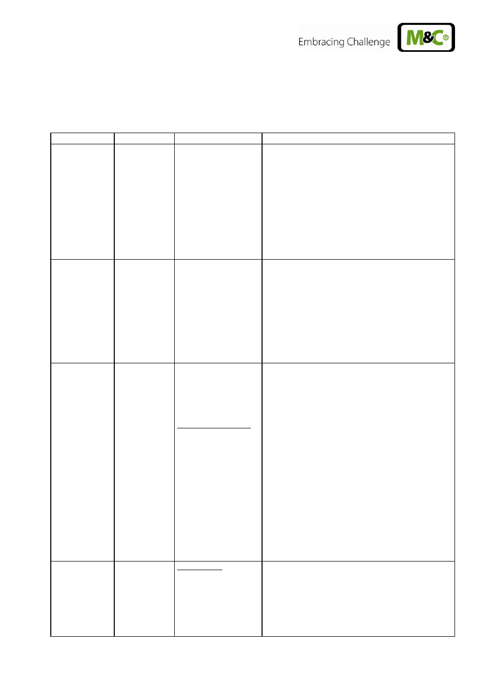
TROUBLE SHOOTING
The following table shows possible sources of errors and how to remove them (not applicable for the
starting-up phase).
Display
Fault
Possible cause
Examination/Correction
None
No supply voltage;
Check the supply voltage according to the type
plate;
ok?
Control whether the mains plug is put in correctly or
whether the main switch is in position „1“;
ok?
Examine the fine fuses F1, F2 on the internal
board;
ok?
LED K1 is
beaming
permanently
and temp. >
8°C
Cooler alarm „Excess
temperature“; cooler
switches the sample
gas pump
automatically off;
Ventilator does not
function
Ambient temperature too high;
ok?
Free convection inside the gas conditioning unit
upset internal temperature too high;
ok?
Sample flow or dew point too high? Reduce flow.
ok?
Return the instrument for repair to M&C.
Temp.
>2°C and
< 7,5°C
Cooler runs,
sample flow is
interrupted;
Alarm-LED in
front panel is
beaming red
(see 4)
Pump
defective
Diaphragm pump
does not work;
Pump is not switched
on
Liquid alarm sensor:
Sensor turns sample
gas pump
automatically off;
Switch in position „on“ (is beaming green)
Ok?
LED Liquid alarm is beaming red.
Liquid in the filter (Dry filter and liquid alarm sensor
and check peristaltic pump, see below.)
ok?
Check the hoses for condensate draining;
ok?
Check pump hose (see 15.3.1);
ok?
Check pump SR25.2 (see 15.3);
ok?
Return instrument for repair to M&C.
Pump works,
but sample
gas flow is
interrupted;
Flow meter :
Needle valve is shut.
Sample probe or
sample hose clogged
or line squeezed;
Set the desired flow rate on the needle valve.
Loosen the sample hose from the sample gas inlet
of the gas conditioning unit (see 12.1);
Gas flow?
Clean the clogged line or replace it;