Figure 2-4 front panel of the dc power module, Figure 2-4 – Panasonic 324566-A User Manual
Page 40
Nortel Secure Router 8012
Hardware Description
2 Power supply
Issue 5.3 (6 April 2009)
Nortel Networks Inc.
2-3
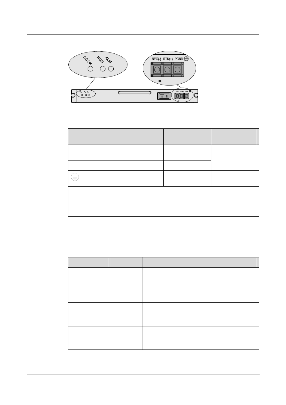
Figure 2-4 Front panel of the DC power module
-48~-60V
-48~-60V
Table 2-1 Relationship of the terminal block connection of the power input cable
Identifier of the
terminal block
Input cable name
Input cable color
Input cable
interface
RTN (+)
Power grounding
cable
Black
NEG (-)
Power cable
Blue
Core end terminal
PGND
Protection
grounding cable
Yellow and green
Need not be
connected.
NOTE
z
RTN: Return
z
NEG: Negative
z
PGND: Protection Ground
As shown in Table 2-2 and Table 2-3, you can view the running state of the power module on
the indicators of the Routing Process Unit (RPU) front panel.
Table 2-2 Description of the indicators on the AC power supply module
Name
Color
Description
AC OK
Green
The power module input LED (only for the AC power
module).
Constant ON means the voltage input is normal (100 V
to 240 V), and OFF means the voltage input is not
normal.
RUN
Green
The power module indicators.
Constant ON means the power module runs normally,
and OFF means the power module has faults.
ALM
Red
The power module fault indicator.
Constant ON means the power module has faults or is
not in position.