Logic 3 RM-DN2 User Manual
Page 10
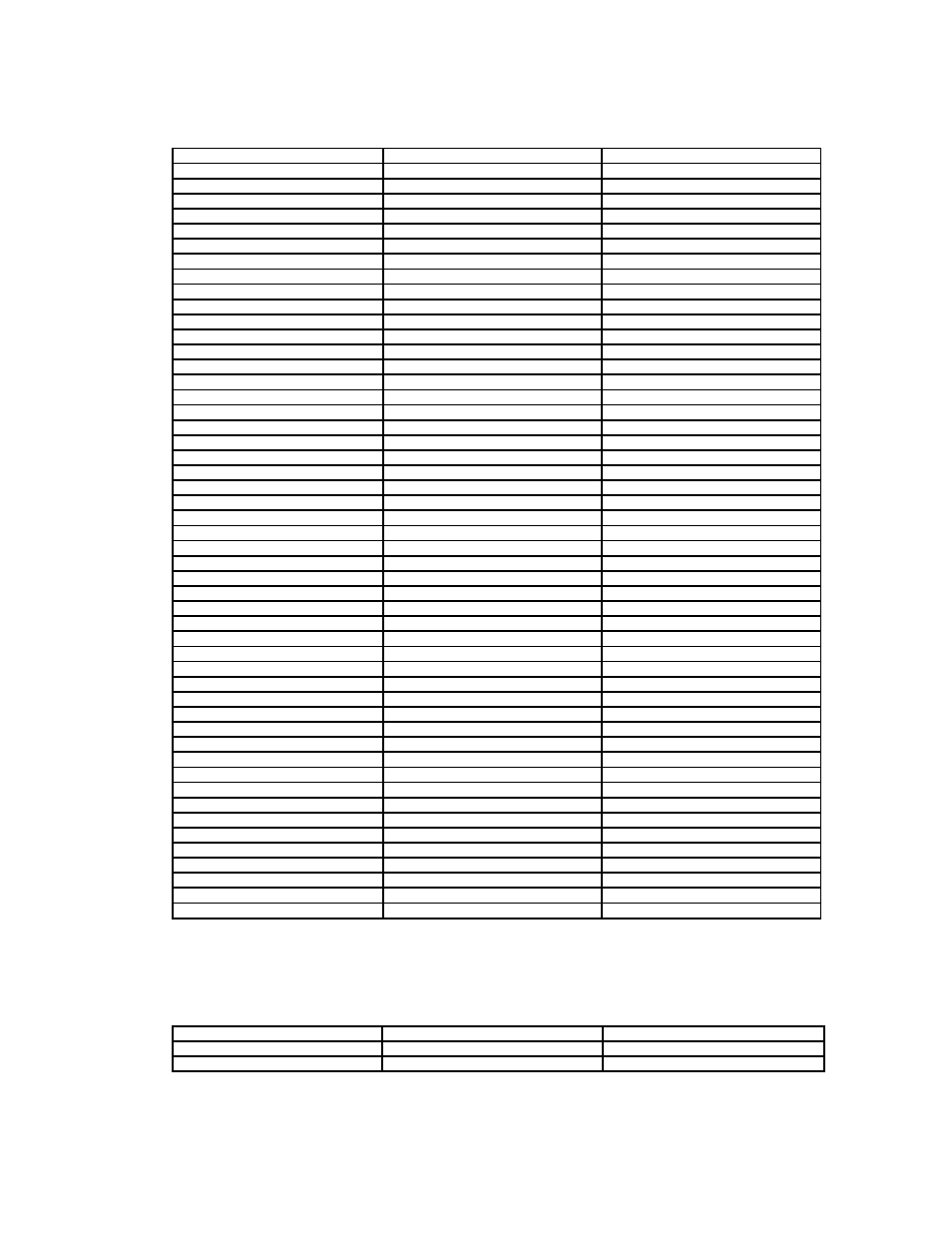
J6 – Compact Flash card connector
PIN
SYMBOL
DESCRIPTION
1
GND
Ground
2
D3
Data bit 3
3
D4
Data bit 4
4
D5
Data bit 5
5
D6
Data bit 6
6
D7
Data bit 7
7
/CE1
Card enable 1
8
GND
Ground
9
GND
Ground
10
GND
Ground
11
GND
Ground
12
GND
Ground
13
VCC
+5V
14
GND
Ground
15
GND
Ground
16
GND
Ground
17
GND
Ground
18
A2
Address bit 2
19
A1
Address bit 1
20
A0
Address bit 0
21
D0
Data bit B3
22
D1
Data bit B4
23
D2
Data bit B5
24
NC
No connection
25
/CD1
Card detect pin 1
26
/CD2
Card detect pin 2
27
NC
No connection
28
NC
No connection
29
NC
No connection
30
NC
No connection
31
NC
No connection
32
/CE2
Card enable 2
33
NC
No connection
34
/RD
Memory read strobe
35
/WR
Memory write strobe
36
NC
No connection
37
IRQ
Interrupt request
38
VCC
+5V
39
GND
Ground
40
NC
No connection
41
RESET
System reset
42
NC
No connection
43
NC
No connection
44
NC
No connection
45
Pin45
BVD2
46
Pin46
BVD1
47
NC
No connection
48
NC
No connection
49
NC
No connection
50
GND
Ground
PP1 - Main power input
PIN
SYMBOL
DESCRIPTION
1
+12_CENTER
+12V DC in center pin
2
GND
Ground
- 10 -