Electrical diagram – La Pavoni EVOLUTION P3 User Manual
Page 5
Pag. 24
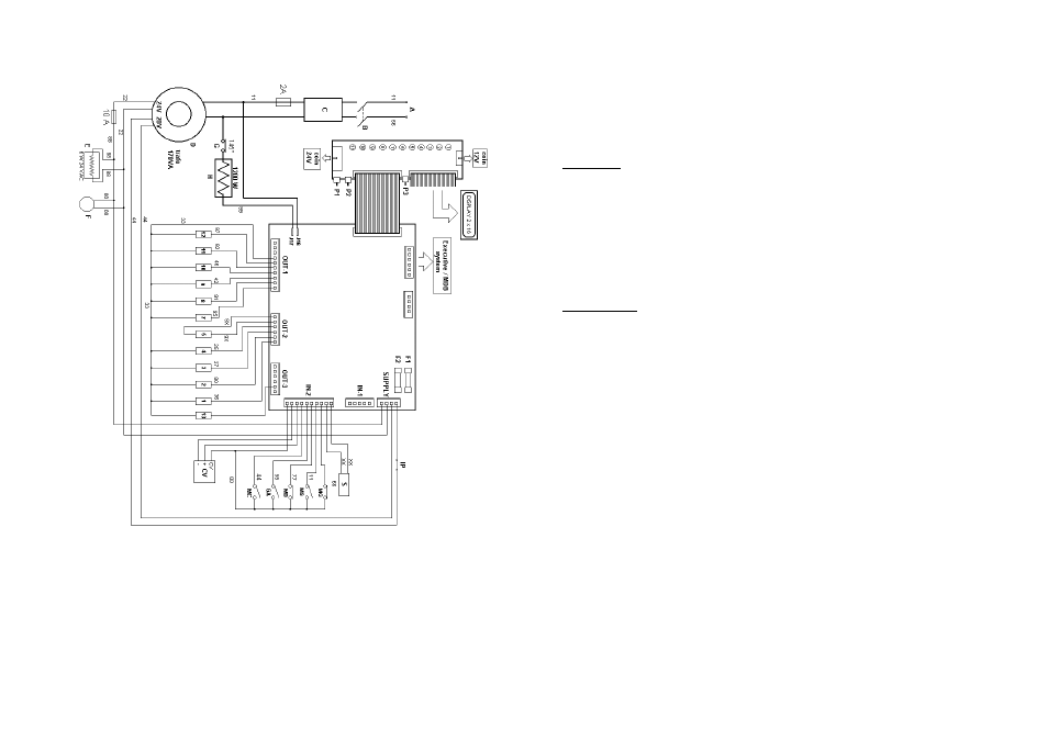
ELECTRICAL DIAGRAM
Pag. 5
HYDRAULIC CONNECTION
The machine could be installed on:
•
a cabinet with place for cups, spoons and sugar and a water tank of 15lt
•
a small base with waste containers (the machine has to be with mains water
connection).
On cabinet
Place the dispenser on the base and fix it with the screws.
Fill up the special water tank with potable water, insert the tube with the
filter and the one-way valve , and if it's present, the float.
Insert in the tank of 5 lt. the waste pipe.
Fix a bag to the apposite hook for the coffee grounds.
Fill the containers, with the apposite products.
On small base
Check the mains pressure doesn’t exceed 2 bar, otherwise it is necessary to
install a pressure-reductor.
Connect the mains pipe to the electro valve.
Verify, through the manometer inside the machine, that the pressure doesn’t
overcome 1 bar, otherwise adjust it with the inside reductor.
Fill the containers, with the apposite products.
PAYMENT SYSTEM CONNECTION
•
VALIDATOR 12V
connect to the keyboard connector COIN12V (see
figure at page 6).
•
VALIDATOR 24V
connect to the keyboard connector COIN12V (see
figure at page 6).
•
EXECUTIVE / MDB connect to the relative cables (optional)
•
SINGLE IMPLUSE SYSTEM (obliterator, token system, etc.) connect to the
connector 6 pins in the right up angle of the machine.
After the electric connection, it is necessary to set the used system into the pro-
gram (see page 13).