System overview, Multiple channel system – Listen Technologies Stationary LA-350 User Manual
Page 13
7
Design Guide Design Guide
Design Guide
System Overview
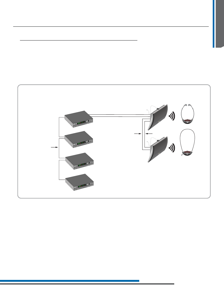
A multiple channel system consists of two to four LT-82 transmitters and one or more radiators. The diagram
EHORZVKRZVVXFKDV\VWHPZLWKWZRUDGLDWRUV7KHUDGLDWRUVDUHSRZHUHGIURPWKHSRZHUVXSSO\IURPWKHÀUVW
transmitter. This power supply can supply enough power for the LT-82 and two LA-140 radiators. If you need
more than two radiators, you can use the power from the other transmitters. In this example, the four
transmitter power supplies can supply enough power for up to eight LA-140 radiators. This is discussed later in
this document. Power issupplied from standard CAT-5 cable while RF from the transmitter is delivered using
50-ohm RG-58 coaxial cable. Each radiator is supplied with 25 feet (7.6 meters) of CAT-5 and RG-58 coaxial
cable.
Multiple Channel System
Up to four LT-82 transmitters can
be daisy chained together (using
RG-58 cable) to create a
multi-channel system
LA -89 RG-58 Multi-carrier
Interconnection Cable (included)
RF – RG-58 50 ohm Cable
RF – RG-58 50 ohm Cable
Up to 100 LA-140 radiators can be daisy chained
together (using RG-58 cable) to provide sufficient
IR power for most applications
LR-42 IR Stetho Receiver
LR-44 IR Lanyard Receiver
Radiator Power: Radiators can be
powered from the LT-82 (up to two
radiators) or an additional power supply
(LA-205) can power up to two radiators
Radiator RF: RF from the last LT-82 must be
daisy chained from radiator to radiator
Power – CAT-5 Cable
Power – CAT-5 Cable
LA-140 IR Radiator
LA-140 IR Radiator
IR
IR
LT-82 Stationary IR Transmitter
LT-82 Stationary IR Transmitter
LT-82 Stationary IR Transmitter
LT-82 Stationary IR Transmitter
1
2
3
4
1
2
3
4