About the technical manual, Installation, Fig. e – Sony XCD-SX710 User Manual
Page 2: Fig. f, Fig. g, Controlling the camera from your pc, Typical ccd phenomena, Specifications
E
4
Installation
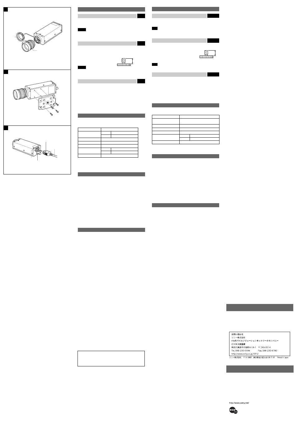
Fitting the lens
Fig. E
1 Remove the lens mount cap.
2 Screw in the lens (not supplied), and turn it until it is secured.
Note
Clean the optical filter with a commercially available blower brush to remove
dust.
Using a tripod
Fig. F
To use the tripod, install the tripod adaptor VCT-ST70I (not supplied) on the
camera module.
Use a tripod screw with a protrusion (
4
) extending
from the installation surface, as follows:
ISO standard: Length 4.5 mm ±0.2 mm
ASA standard: Length 0.197 inches
Note
If you install a tripod adapter (not supplied), use the screws provided.
Connecting the camera cable
Fig. G
Connect the IEEE1394 camera cable to the camera connector and the 1394
interface connector of your computer. When you connect the cable, press
the push button on the connector and insert the connector until it snaps into
place.
1
Camera connector
2
TRIG IN connector
3
Push button
4
IEEE1394 camera cable (supplied)
Controlling the camera from your PC
You can control the camera from your PC. The following table shows the
control functions.
Control functions
*
Description
Frame rate
XCD-SX910 : 15/7.5/3.75/1.875 fps
XCD-X710
: 30/15/7.5/3.75/1.875 fps
Transmission speed
400M/200M bps
Gain
0 ~ +18 dB
Shutter speed
1
/
100000
~ 17.5 seconds
External trigger function
Mode 0
Setting by register value
Mode 1
Setting by trigger pulse width
Partial Scan function
16
×
16 : 256 devided
*
The frame rates and the other controllable functions comply with digital camera
protocol Ver. 1.30 defined by the serial digital bus standard IEEE1394.
Typical CCD Phenomena
The following effects on the monitor screen are characteristic of CCD
cameras. They do not indicate any fault with the camera module.
Smear
This occurs when shooting a very bright object such as electric lighting, the
sun, or a strong reflection.
This phenomenon is caused by an electric charge induced by infrared
radiation deep in the photosensor. It appears as a vertical smear, since the
CCD imaging element uses an interline transfer system.
Vertical aliasing
When you shoot vertical stripes or lines, they may appear jagged.
White speckles
When you shoot a dark object at a high temperature, small white dots may
appear all over the image.
Specifications
Pickup device
Progressive scan CCD
Effective picture elements:
XCD-SX910 : 1392
×
1040 (horizontal/vertical)
XCD-X710 : 1034
×
779 (horizontal/vertical)
Interface
IEEE1394-1995
Output signal format
XCD-SX910 : Standard : 1280
×
960 (horizontal/
vertical)
Maximum : 1376
×
1024 (horizontal/
vertical)
XCD-X710 : 1024
×
768 (horizontal/vertical)
Frame rate
XCD-SX910 : 15/7.5/3.75/1.875 fps
XCD-X710 : 30/15/7.5/3.75/1.875 fps
Transfer speed
400M/200M bps
External trigger signal (conditions)
Pulse width : 10
µ
s or more
Polarity
: Negative
Amplitude
: TTL level
Lens mount
C mount
Flange back
17.526 mm
Minimum illumination
4 lx (F0.95, Gain: +18dB)
Gamma
γ
= 1
Gain
0 ~ +18 dB
Shutter speed
1/100000 ~ 17.5 seconds
Power
DC +8V to +30V (from IEEE1394 camera cable)
Power consumption
4.5W
Operating temperature: –5 to +45°C (23 to 113°F)
Storage temperature:
–30 to +60°C (–22 to 140°F)
Operating relative humidity:
20 to 80% (no condensation)
Storage relative humidity:
20 to 95% (no condensation)
Vibration resistance
10G (20Hz ~ 200Hz)
Shock resistance
70G
External dimension (w/h/d)
44
Ч
33
Ч
116 mm
(1
3
/
4
Ч
1
5
/
16
Ч
4
5
/
8
inches)
Mass
250g (9 oz)
Accessories
IEEE1394 camera cable (1)
Lens mount cap (1)
Operating Instructions (1)
Design and specifications are subject to change without notice.
4
About the Technical Manual
The Operating Instructions describe the functions and use of this
product.
For more details, see the Technical Manual. Please ask your sales
representative about the Technical Manual.
F
G
E
1
2
F
VCT-ST70I
4
ISO
4
4.5mm 0.2mm
ASA
4
0.197
G
IEEE1394
1394
1
2
TRIG IN
3
4
IEEE1394
SX910
15/7.5/3.75/1.875 fps
X710
30/15/7.5/3.75/1.875 fps
400M/200M bps
0 +18 dB
1
/
100000
17.5
Mode 0
Mode 1
16 16 256
IEEE1394
Ver. 1.30
CCD
CCD
CCD
CCD
XCD-SX910 : 1392 1040
XCD-X710 : 1034 779
IEEE1394–1995
XCD-SX910 :
1280 960
1376 1024
XCD-X710 : 1024 768
XCD-SX910 : 15/7.5/3.75/1.875 fps
XCD-X710 : 30/15/7.5/3.75/1.875 fps
400M/200M bps
: 10 s
:
: TTL
C
17.526 mm
4 lx F0.95, Gain: +18dB
1
0 +18 dB
1
/
100000
17.5
IEEE1394
DC +8V +30V
4.5W
5
45
30
60
20 80 (
)
20 95 (
)
10G (20Hz 200Hz)
70G
44 (W) 33 (H) 116 (D)mm
250g
IEEE1394
(1)
(1)
(1)
Digital Interface
1
2
Digital Interface
Digita
l Inte
rface
2
1
4
3
VCCI
B
100%
Printed on 100% recycled paper.