Front panel layout – Samson MDR10 User Manual
Page 6
4
1
2
3
4
5
6
7
8
10
11
12
14
15
16
17
18
19
20
21
22
23
24
25
28
27
26
29
30
31
32
33
34
35
36
37
38
39
40
41
42
43
44
45
46
47
48
49
50
51
52
53
54
55
56
9
13
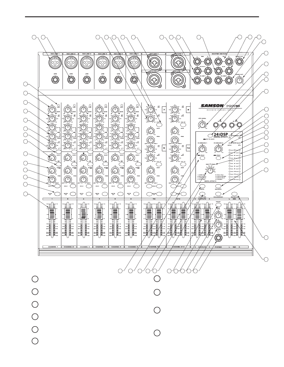
Front Panel Layout
1
CLIP
– Red LED will illuminate, indicating when the GAIN
control has been adjusted too high.
2
GAIN
– Used to set the input level of the mic pre and line
input.
3
HIGH FREQUENCY
- Controls the high band level of the
Channel Equalizer, +/- 15 dB.
4
MID CUT & BOOST
- Controls the level of mid-range ,+/- 15
dB at the frequency set by the Mid Frequency control.
5
MID FREQUENCY
- Used to set the center point of the mid
band of the Channel Equalizer from100 Hz to 5KHz.
6
LOW FREQUENCY
- Controls the low band of the Channel
Equalizer, +/- 15 dB at 80Hz.
7
LOW CUT
– Bass roll off switch at 80Hz used to eliminate
unwanted low end rumble and hum.
8
AUX 1
– Pre fader auxiliary send that can be used with an
external effects processor, or to create a cue or monitor
mix.
9
AUX 1 PRE/POST Switch
This LED back-lit switch is used
to select the point in the audio path that the channel’s sig-
nal is sent to the AUX 1 bus, either before or after the
input fader.
10
AUX 2/DSP
– Post fader auxiliary send connected to the
internal 24 BIT DSP effect processor and can also be
used with an external effects processor.