Iomega EP510 User Manual
Page 4
M
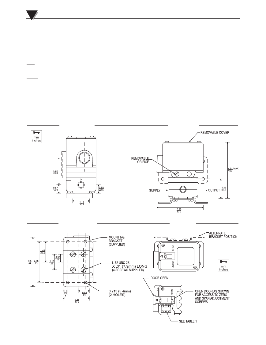
EP510 AND IP510
OUNTING
GENERAL
NEMA 1 and NEMA 4X transducers can be mounted in any position.
DIRECT MOUNTING
PIPE
•
Any NEMA 1 transducers may be supported by its own plumbing for air supply and output. NEMA 4X transducers may
also be supported using 1/2" explosion proof conduit in the electrical port.
PANEL
•
NEMA 1 transducers may be mounted to a panel with two No. 10-32 screws using threaded holes in the back of a trans-
ducer or with two to four No. 8-32 screws using threaded holes in the bottom of a transducer.
•
NEMA 4X transducers may be mounted to a panel with three No. 10-32 screws using threaded holes in the back of a
transducer or with four No. 8-32 screws using threaded holes in the bottom of a transducer. In the case of back-mount-
ing, if the panel extends towards the screw-on cover, a 3/16-inch-thick spacer MUST be used between the back of the
transducer and the panel in order for the panel to clear the transducer's screw-on cover.
M-4109/1104 IP510, EP510, IP511, EP511 SERIES
A
4
W
E
I
V
E
D
I
S
W
E
I
V
T
N
O
R
F
W
E
I
V
P
O
T
W
E
I
V
M
O
T
T
O
B
Drawings and dimensions are for reference only.