Ultra, Sport, Floodlight – GE UltraSport User Manual
Page 9
9
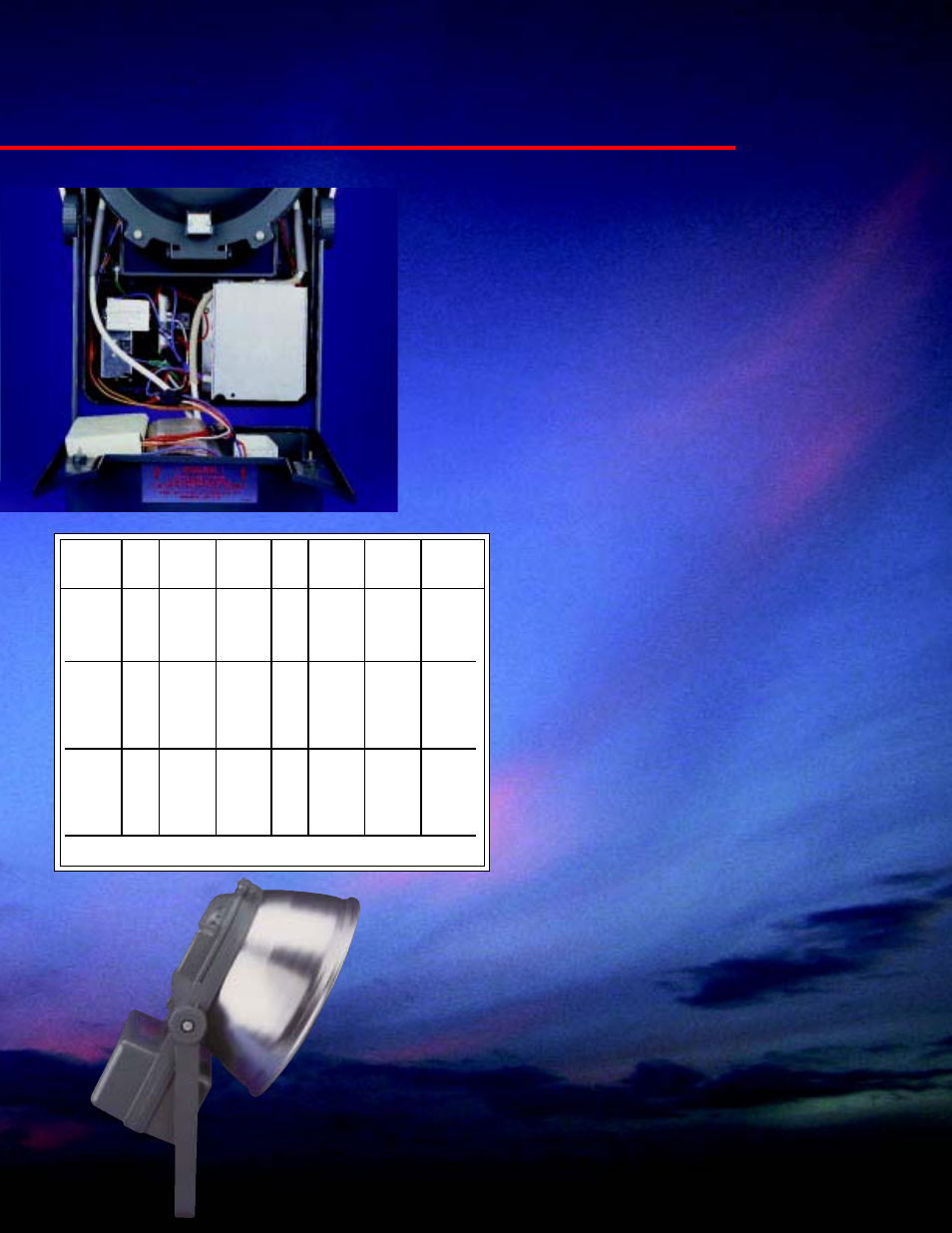
Ballast System—
All Ultra
★
★
★
★
★Sport floodlights feature the new
compact GE Accuwatt
TM
ballast system in which the ballast is
direct mounted to the aluminum housing with a thermal wedge
for optimum heat transfer.
GE Accuwatt
TM
2000, 1500 and 1000 watt auto-regulator circuits
are designed to start and stabilize their respective double-ended
metal halide lamps at their design center.
Ballast dielectric material is rated for a 200 degree C maximum
operating temperature.
Every ballast undergoes a 2500 volt RMS “High Pot” and a
10KV “til” test in accordance with ANSI C82.4, C82.6 and C92.1
specifications. The ballast circuits are also designed to sustain a
nominal lamp over a line voltage dip of 50% for up to four
seconds when operating at nominal line voltage according to
ANSI specification C82.6.
Ultra
✭
Sport
TM
Floodlight
e
Optional System 2
TM
Bi-Level Controls—
The choice of
high/low two-level lighting is also available. System 2 Bi-Level
controls utilize a 15 volt AC signal that is hard wired to the
floodlight to switch capacitance and change wattage.
The 2000/1500 watt and 1500/1000 watt system choices are
available for separate game time and practice light levels.
The ballast circuit will reliably start and stabilize a
nominal lamp in ambient temperatures down to -29
degrees C. The unit is rated for operation in up to
40 degree C ambient temperatures.*
Ballast Maintenance—
Electrical access is
achieved from the rear of the fixture without any
adjustment to the aiming required. The rear
housing cover is held in place by four captive
corrosion-resistant cad-polymer coated screws.
Optional Instant Hot Restart—
The
Ultra
★
★
★
★
★Sport floodlight can be ordered with a new
optional instant hot restart feature. After a
momentary power interruption or line voltage dip
which causes the lamp to extinguish, a 34KV hot
restart circuit will restart the lamp within two
seconds of re-application of power.
% Allow-
able Line
Line
Power
Line
% Allow-
Line
Voltage
Operating
Line
Factor
Starting
able Line
Watts
Volts
Variation
Amperes
Watts %
Amperes
Voltage Dip
2000
208
11.2
2125
10.0
*25°C
240
9.5
2115
8.5
Max
277
8.3
2115
7.2
Ambient 347
±10
6.6
2122 90+
5.6
50
480
4.8
2132
4.4
1500
120
14.4
1630
11.2
*40°C
208
8.5
1630
6.9
Max
240
7.3
1630
5.6
Ambient 277
±10
6.3
1630 90+
4.7
50
347
4.8
1620
3.9
480
3.7
1630
2.8
1000
120
9.0
1080
6.6
*40°C
208
5.4
1070
4.1
Max
240
±
4.8
1080 90+
3.5
50
Ambient 237
4.1
1080
2.9
347
3.6
1070
2.9
480
2.6
1088
1.8
NOTE: For 50Hz voltages, contact factory.
*See ballast table for wattage limitations.