Installation, Warning, Locating grill/built-in clearances – Fisher & Paykel BGB48 User Manual
Page 13: Important, General, Insulated jacket, Clearances to combustible construction
11
GENERAL
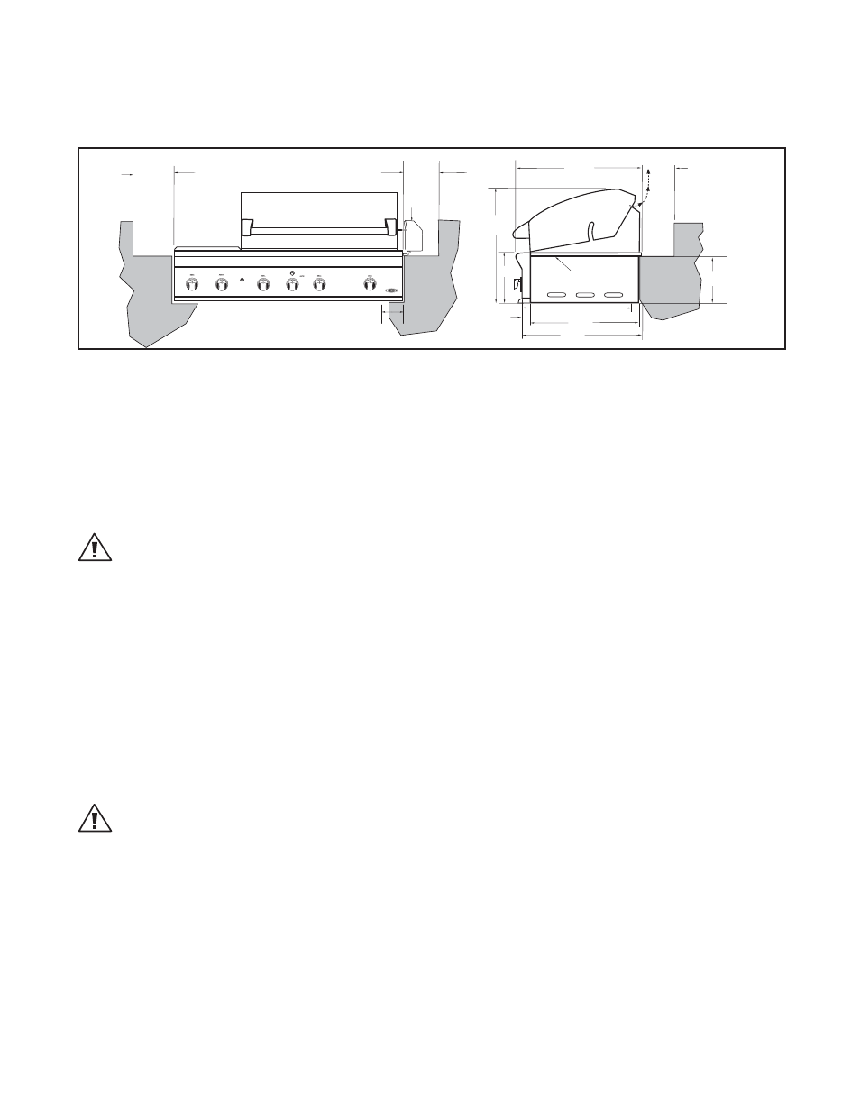
The grill is designed for easy placement into built-in masonry enclosures. For non-combustible applications the
grill drops into the opening shown in Fig. 10 and hangs from its side flanges. A deck is not required to support it
from the bottom. When using the insulated jacket in a combustible enclosure application, see the bottom of
Fig. 10. The insulation jacket assembly must be supported from the bottom by a ledge on each side and back or a
solid deck.
A carpenter’s “spirit level” should be used to assure that the unit is level both front-to-back and side-to-side. If it
is not level, burner combustion may be erratic or the unit may not function efficiently for grease flow. If the floor
is uneven or has a decided slope, re-leveling may be required after each moving of a freestanding unit.
INSULATED JACKET:
WARNING!
Installing this product into a combustible enclosure without an insulated jacket could result in fire, property damage
and personal injury.
If the grill is to be placed into a combustible enclosure, an approved insulated jacket is necessary. Insulated
jackets are available from your dealer. Use only the DCS by Fisher & Paykel insulated jacket which has specifically
been designed and tested for this purpose. Review the detail drawing shown (Fig. 10) and take into account the
provisions shown for gas line hook-up clearance in the right rear corner. It is required that ventilation holes are
provided in the enclosure to eliminate the potential build-up of gas in the event of a gas leak. The supporting
ledges or deck must be level and flat and strong enough to support the grill and insulated jacket. The counter
should also be level.
INSTALLATION
LOCATING GRILL/BUILT-IN CLEARANCES
648 mm
559 mm
562 mm
centre of gas inlet
rotisserie
motor
616 mm
267 mm
673 mm
grill
exhaust
min. 310 mm (to combustible
construction)
254 mm
51 mm
Bottom of
support flange
min. 310 mm
min. 310 mm
81 mm
centre of gas inlet
FIG. 9
Clearances to Combustible Construction**
** DEFINITION OF COMBUSTIBLE MATERIAL -
Any materials of a building structure or decorative structure made
of wood, compressed paper, plant fibers, vinyl/plastic or other materials that are capable of transferring heat or
being ignited and burned. Such material shall be considered combustible even though flame-proofed, fire-retar-
dant treated or surface-painted, or plastered.
Important!
It is required that a minimum of 3 x 65 cm
2
of ventilation opening be provided for both the left and right sides,
as well as the back of enclosure (Fig. 10), in order to safely dissipate unburned gas vapours in the event of a
gas supply leak.
WARNING!
Note specific built-in enclosure ventilation requirements. See text and Fig. 10.