Furuno FELCOM 250 User Manual
Page 24
1. HOW TO INSTALL THE UNIT
18
How to mount
The mounting dimensions are shown in
the outline drawing at the back of this
manual. Determine the mounting loca-
tion, leaving sufficient space around the
unit, and then fix the mounting base to
the mounting location. The mounting
base is different for bulkhead and desk-
top mounts, however the mounting pro-
cedure is the same for all.
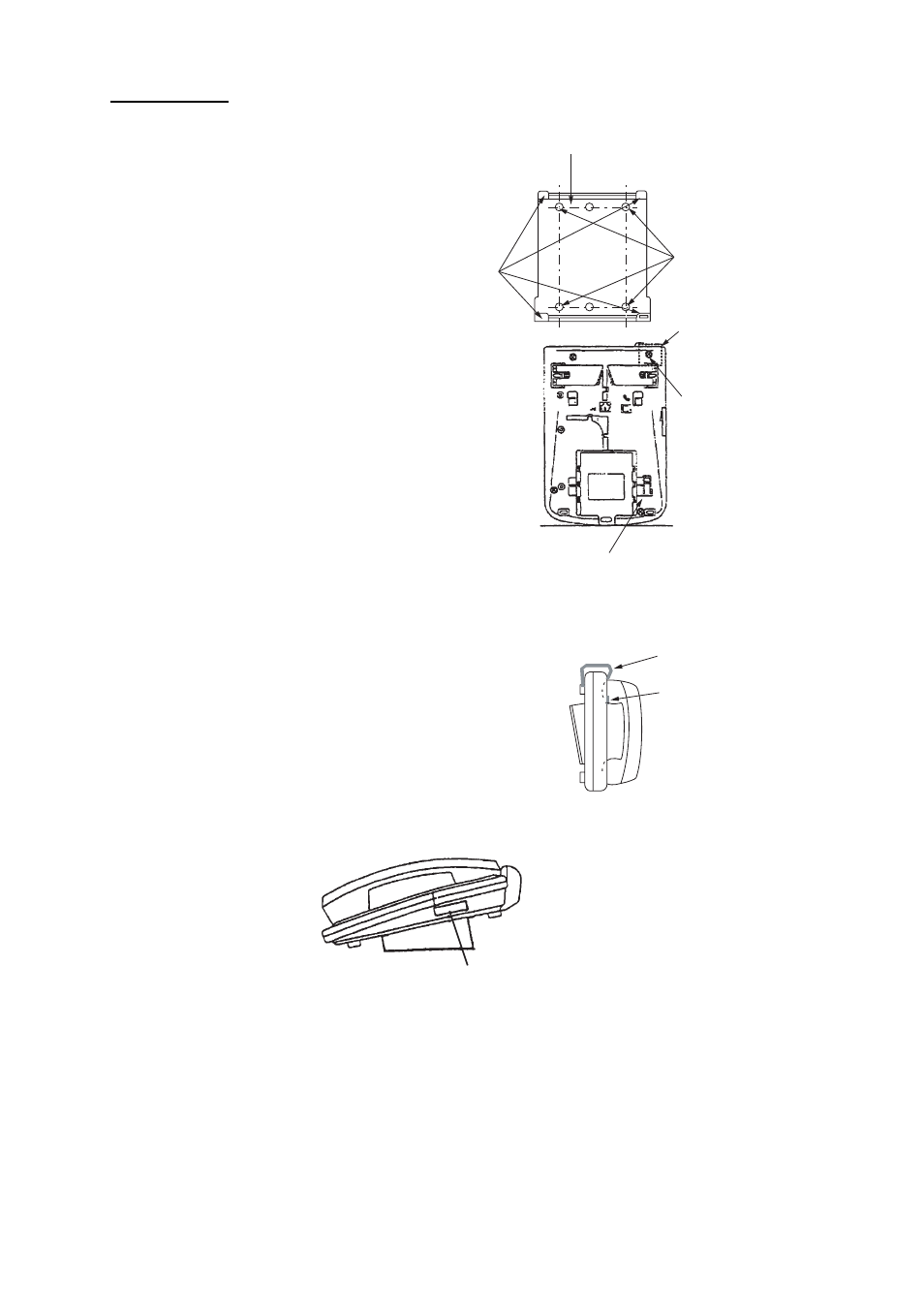
1. Set the mounting base to the mount-
ing location with four self-tapping
screws (4x16).
2. On the bottom of the telephone, re-
lease the screw shown in the figure.
(The screw may be discarded.) At-
tach the vulcanizing tape (supplied)
to the handset fixture. Fasten the
handset fixture to the bottom of the
telephone with a screw (3x14, sup-
plied).
3. The catch in the receiver cradle func-
tions to hang up the handset. Set the
catch in the upward position. To de-
tach the handset from the hanger,
slide the handset upward.)
4. Set the telephone to the four catches
in the mounting base, then slide it to-
ward you until you hear a click.
5. Attach the "SLIDE" label (supplied) to
the handset.
6. Attach the label (16-007-6927-0) for compass safe distance as shown below.
7. Set the line type of telephone to PB (Push Button) type from DP (Dial Pulse) type as follows.
Mounting base
(Desktop: Use installation materials,
Bulkhead: Use telephone accessories.)
Secure mounting
base with tapping
screws.
Attach handset
fixture here.
Unfasten this screw.
Bottom view
Mounting base stopper
Handset fixture
Catch
Catches
Label (16-007-6927-0)