Electrical specifications – Honeywell IS4911 User Manual
Page 23
19
Electrical Specifications
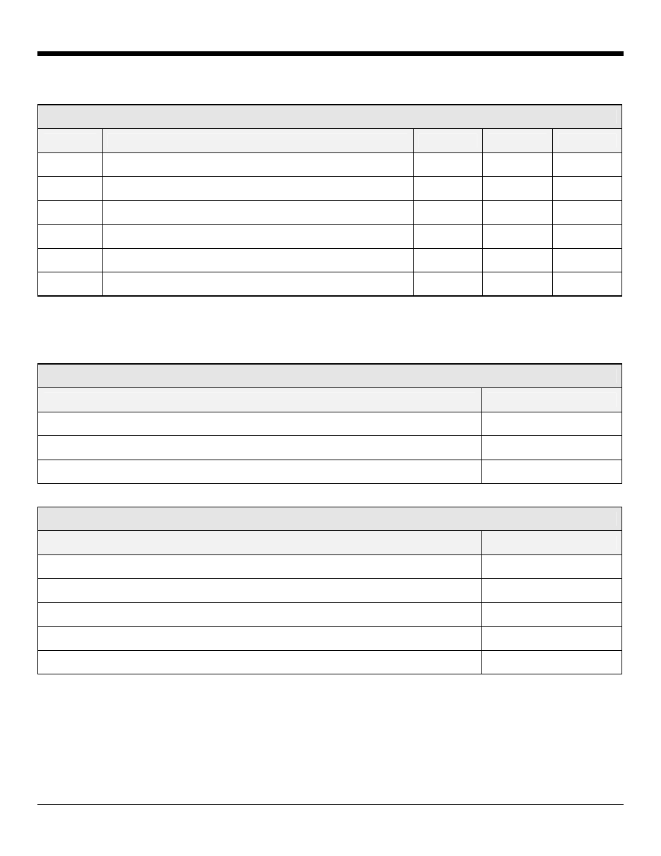
Signal Levels
Signal
Description
Min.
Typical
Max.
Vimager
Power to Imager and Supporting Circuitry
3.1V
3.3V
3.5V
VLED
Power to Illumination and Targeting LEDs
3V
-
5.5V
VIL1
Input Low (Aimer, Illum_On, Trigger)
.6V
VIH1
Input High (Aimer, Illum_On, Trigger)
2.1V
Vimager
VOH2
Output High Voltage (Data, PCLK, VSYNC, HSYNC)
2.71
VOL2
Output Low Voltage (Data, PCLK, VSYNC, HSYNC)
.3V1
1
Sink / Source current = 2mA
2
Voltages listed are at the engine. A voltage drop should be expected when using a flex cable.
V_Imager Current (Vimager = 3.3V)
Description
Typical
Stand By Current (V_imager = 3.3V)
450 µA
Idle Current (V_camera = 3.3V)
55 mA
Operating Current (V_camera = 3.3V)
90 mA
VLED Current
Description
Typical
idle (VLED = 5V or 3.3V)
50 µA
Peak Current (VLED = 5V or 3.3V) Note: Peak duration of less than 20µS
350 mA
LED enabled (VLED = 5V)
90 mA
LED enabled (VLED = 3.3V)
155 mA
Targeting LED
24 mA
See page 11 for information on system considerations.