Controlled device identification – Grass Valley Switcher Products User Manual
Page 98
98
Switcher Products — Protocols Manual
Section 3 — Peripheral Bus II Protocol
Controlled Device Identification
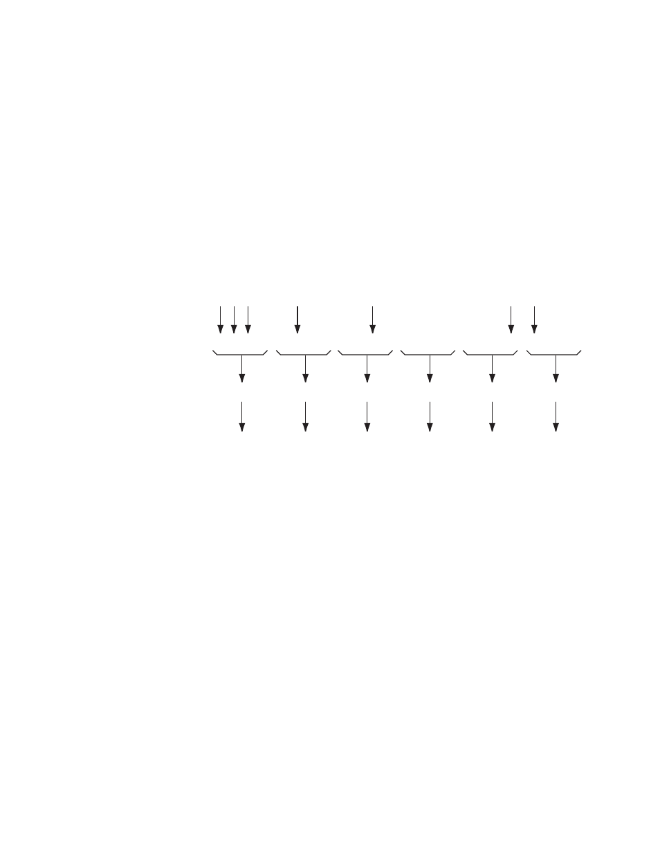
Because the controlling device communicates with multiple controlled
devices, a mechanism is required to specify which device a particular
command is intended for. It is also desirable to be able to send the same
command to multiple devices simultaneously.
PBus II commands employ a six-byte field of ASCII characters (dddddd)
representing six hex numbers to specify which controlled devices are to
receive the command. The six hex numbers represent a binary 24 bit map.
A set bit (1) in the map means the controlled device assigned to that bit
number is included, and a (0) bit means the controlled device is not
included (see
Figure 8. Controlled Device Selection Data Interpretation
8063_02_06_r2
Decimal Controlled Device
Numbers 0-23
Binary Map Indicating
Which of the
Devices Are Selected
Hexadecimal Numbers Equivalent
to Bindary Map Numbers
6-Byte ASCII Character Field
Equivalent to Hexadecimal Numbers
Identifying Selected Devices
23 22 21 20
1 1 1 0
E
45
19 18 17 16
0 1 0 0
4
34
15 14 13 12
0 0 1 0
2
32
11 10 9 8
0 0 0 0
0
30
7 6 5 4
0 0 0 1
1
31
3 2 1 0
1 0 0 0
8
38