Pre out, main in terminals, 8english – Marantz PM-14mkII User Manual
Page 9
8
ENGLISH
How to use the remote control unit
1. Remote control unit
The distance between the signal transmitter of the remote control unit
(RC-17mk
II
PM) and the IR SENSOR of the integrated amplifier (PM-
14mk
II
) should be less than about 5 meters. To ensure remote control,
the remote control unit should be pointed accurately toward the IR SEN-
SOR and there should be no obstacle between the remote control unit
and the IR SENSOR.
Remote controllable range
Stereo integrated amplifier (PM-14mk
II
)
Remote control unit (RC-17mk
II
PM)
2. Loading batteries
The service life of the batteries used in the remote control unit is about
1 year under normal use.
Remove the batteries when the remote control unit is not to be used for
a long period of time. Replace batteries early whenever they seem to
be weakened.
q
Remove the back cover.
w
Insert batteries with correct and polarity.
e
Slide close the battery cover until it clicks.
Improper use of batteries may cause the risk of fluid leakage or
explosion.
Be specially careful in the following points.
q
Insert the batteries with the correct and polarity as indicated
inside the battery case.
w
Do not use a brand-new battery and used battery together.
e
Dry cell batteries may produce different voltages even when
their shapes are the same. Do not use different types of batter-
ies together.
r
Some batteries are rechargeable and some are not. Be sure
to read the caution and instructions described on each bat-
tery.
t
Used batteries should be disposed of in compliance with the
treatment method specified for your local area.
REP
EAT
PH
ON
O
CD
RAN
DO
M
TAP
E 1
LINE
1/TU
NER
+ / A
TAP
E 2
LIN
E 2/T
V
+ / A
LINE
3/D
VD
1
2
3
4
5
6
7
8
9
0
OPE
N
/CLO
SE
VOL
UM
E
Approx. 5 m
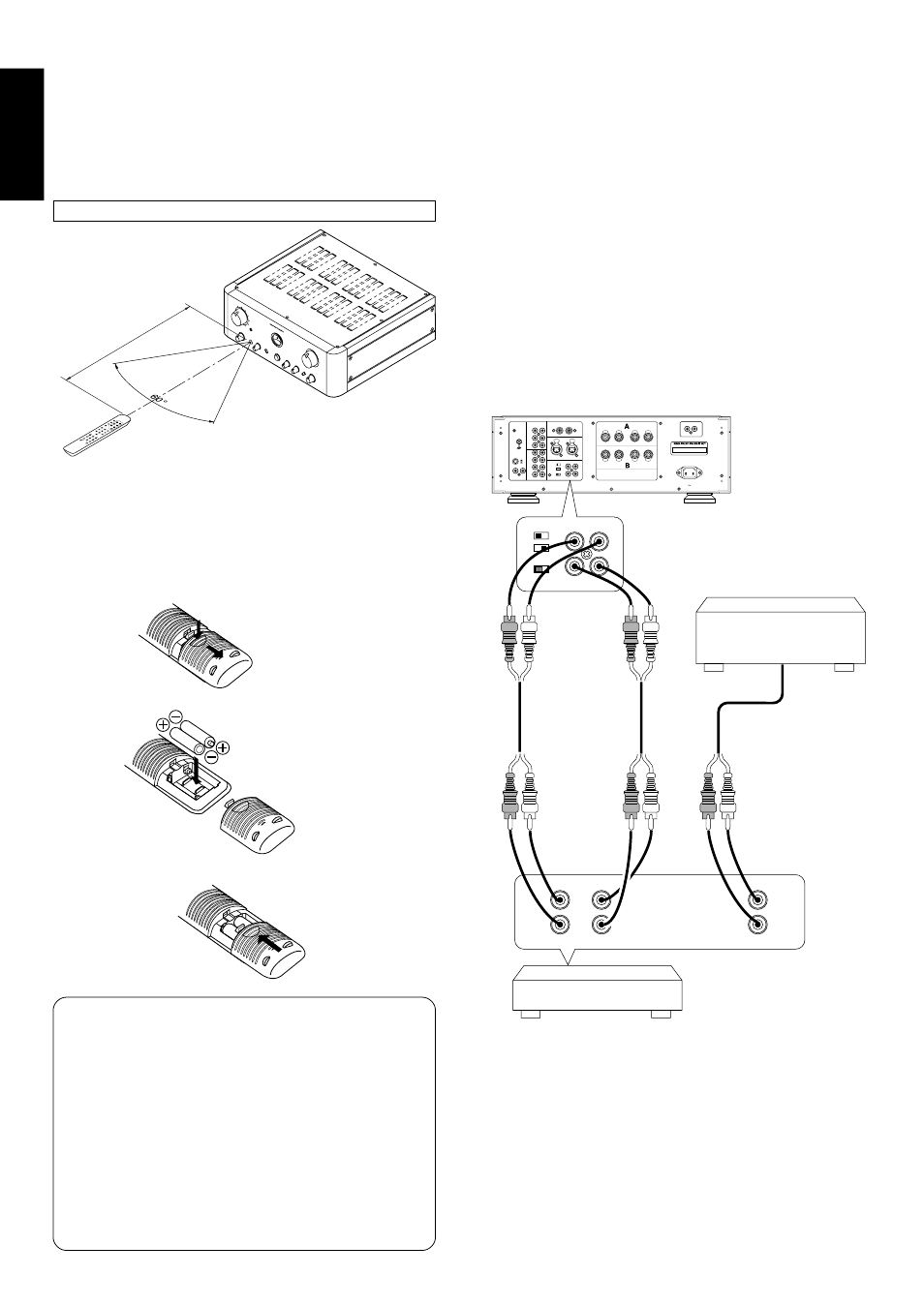
PRE OUT, MAIN IN TERMINALS
When shipped from the factory, the COUPLED/SEPARATE switch is
set to the COUPLED position. In this condition, the PRE OUT (pre amp
output terminal) and MAIN IN (main amp input terminal) are internally
connected, and can be used as the pre main amp. Therefore, it is not
necessary to insert a short bar in the terminals.
If the COUPLED/SEPARATE switch is set to the SEPARATE position,
the PRE OUT (pre amp output terminal) and MAIN IN (main amp input
terminal) can be used individually.
Connect peripheral equipment such as power amps, channel dividers,
sound effectors, etc to the PRE OUT (pre amp output terminal).
Connect the pre amp to the MAIN IN (main amp input terminal).
The diagram below is an example of connecting a channel divider and
expanding it into a multi amp drive.
IN
IN
PUSH
PUSH
GND
LINE
2
LINE
3
LINE
1
R
L
CD UNBALANCED
R
L
CD BALANCED
R
L
CONNECTION 1 – GND 2 – COLD 3 – HOT
SEPARATE
PRE OUT
R
L
R
L
COUPLED
MAIN IN
OUT
OUT
CD-R
TAPE
SELECTOR
MM
MC
R
L
PHONO
+
R
–
–
L
+
+
R
–
–
L
+
S P E A K E R S Y S T E M S
S Y S T E M A : 4 – 16 OHMS
S Y S T E M B : 4 – 16 OHMS
S Y S T E M A + B : 8 – 16 OHMS
AC INLET
HIGH
OUTPUT
L
R
INPUT
L
R
LOW
OUTPUT
SEPARATE
PRE OUT
R
L
R
L
COUPLED
MAIN IN
R
REMOTE CONTROL
IN
OUT
/TUNER
Other power amplifier
Channel divider