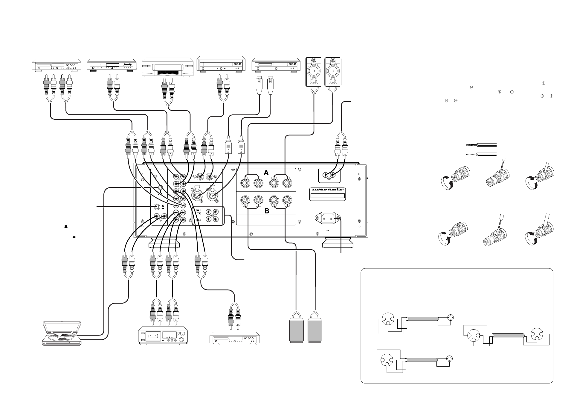
Remote control jacks, Cd player speaker system, Speaker connections – Marantz PM-14mkII User Manual
Page 13: Speaker cord connection
1
PUSH
PUSH
R
GND
R
L
CD UNBALANCED
R
L
CD BALANCED
R
L
CONNECTION 1 – GND 2 – COLD 3 – HOT
SEPARATE
PRE OUT
R
L
R
L
COUPLED
MAIN IN
SELECTOR
MM
MC
R
L
PHONO
+
R
–
–
L
+
+
R
–
–
L
+
S P E A K E R S Y S T E M S
S Y S T E M A : 4 – 16 OHMS
S Y S T E M B : 4 – 16 OHMS
S Y S T E M A + B : 8 – 16 OHMS
AC INLET
REMOTE CONTROL
IN
OUT
IN
IN
LINE
2
LINE
3
LINE
1
OUT
OUT
CD-R
TAPE
/TUNER
L
R
CD Recorder
TAPE DECK
DVD PLAYER, etc
TURNTABLE
VCR, etc
TUNER, etc
CD PLAYER
To AC power outlet
SPEAKER SYSTEM
PHONO SELECTOR switch
L
R
Connect the output cord
from an analog record
turntable.
(To LINE INPUT
jacks)
CD PLAYER
SPEAKER SYSTEM
Connect the R output
terminal to the right channel
speaker and the L output
terminal to the left channel
speaker.
(To LINE
OUTPUT
jacks)
(To LINE
OUTPUT
jacks)
(To LINE OUTPUT
jacks)
(To LINE OUTPUT
jacks)
(To LINE INPUT
jacks)
Connect a power amp,
channel divider, sound
effector, pre main amp,
etc to the PRE OUT
terminal.
Connect the pre amp to
the MAIN IN terminal.
For the details, refer to
page 8.
REMOTE CONTROL jacks
By connecting this unit with a MARANTZ
component equipped with the remote
control (D-BUS) jacks, both components
can be remote control as a system.
For details of the remote control function,
read the user guide of the connected
component.
Set according to the type of cartridge used
withthe turntable
MM (Moving Magnet) type
Leave the switch in the out (
) position.
MC (Moving Coil) type
Set the switch to the pressed-in (
) position.
• Banana plug can also be used as shown
Tu r n t h e t e r m i n a l
counterclockwise to
loosen.
Insert the conductors.
Strip coating from
the end of cord.
• The TAPE 1 and TAPE 2 program source can also accept the connections with the audio output/input jacks of VCR, etc
68
69
1
2
3
GND
HOT
COLD
(XLR)
HOT
GND
1
2
3
GND
HOT
COLD
(XLR)
HOT
GND
A USA system (wPIN=COLD ePIN=HOT)
B
European system (wPIN=HOT ePIN=COLD)
GND
HOT
GND
1
2
3
COLD
(XLR)
1
2
3
HOT
COLD
(XLR)
To BALANCED
connector
(XLR connector)
SPEAKER CONNECTIONS
This unit can accept the connection of speakers equipped with
dedicated terminals for bi-wire connection.
Bi-wire connection is possible by connecting each speaker to both
the SYSTEM A and SYSTEM B terminals.
Speakers which do not use bi-wire connection or which are not
equipped with bi-wire connection terminals can be connected to either
SYSTEM A or SYSTEM B terminals.
However, in this case, it is recommended to use the SYSTEM A
terminals in consideration of sound quality.
• Speakers connected to this unit should have an impedance in the
range of 4 to 16 ohms. If speakers with an impedance of less than
4 ohms are connected, the internal protection circuitry may switch
on to cut the output during operation.
• This unit’s speaker terminals are separated into positive (
: red)
and negative (
: white) polarity. The terminals on the speakers
are also separated by polarity (
and
). When making connec-
tions, be sure to connect terminals of the same polarity (
to
,
to
).
NOTE:
In case of using two sets of speakers simultaneously, make sure the
impedance of each speaker is 8 ohms or greater. If speakers with an
impedance of less than 8 ohms are connected, the internal protection
circuitry may switch on causing normal stereo operation to be
prevented.
SPEAKER CORD CONNECTION
Banana
plug
Turn the terminal
c l o c k w i s e t o
clamp speaker
cord.
Tu r n t h e t e r m i n a l
counterclockwise to
loosen.
Insert the banana plug
Turn the terminal
clockwise to clamp
banana plug
CD BALANCED terminal
1. The XLR connector is used in the BALANCED
terminal.
2. For professional usage, there are two types of XLR
connector connection method.
3. The USA system is used in this device (PM-14mkII).
When using an XLR connector cable and playing
a CD player etc which uses the European system,
the phase is reversed. In this case, as shown in
the diagram below, reconnect the q PIN and w
PIN of one side of the XLR connector to make it
the USA system.
The above will ensure that the equipment is played
with the correct phase.
PM-14mkII (USA system)
(European system)
Twist conduc