Winco 2FS Generators 2000 Watt Belt Drive User Manual
Page 8
2095-0
8
60706-230
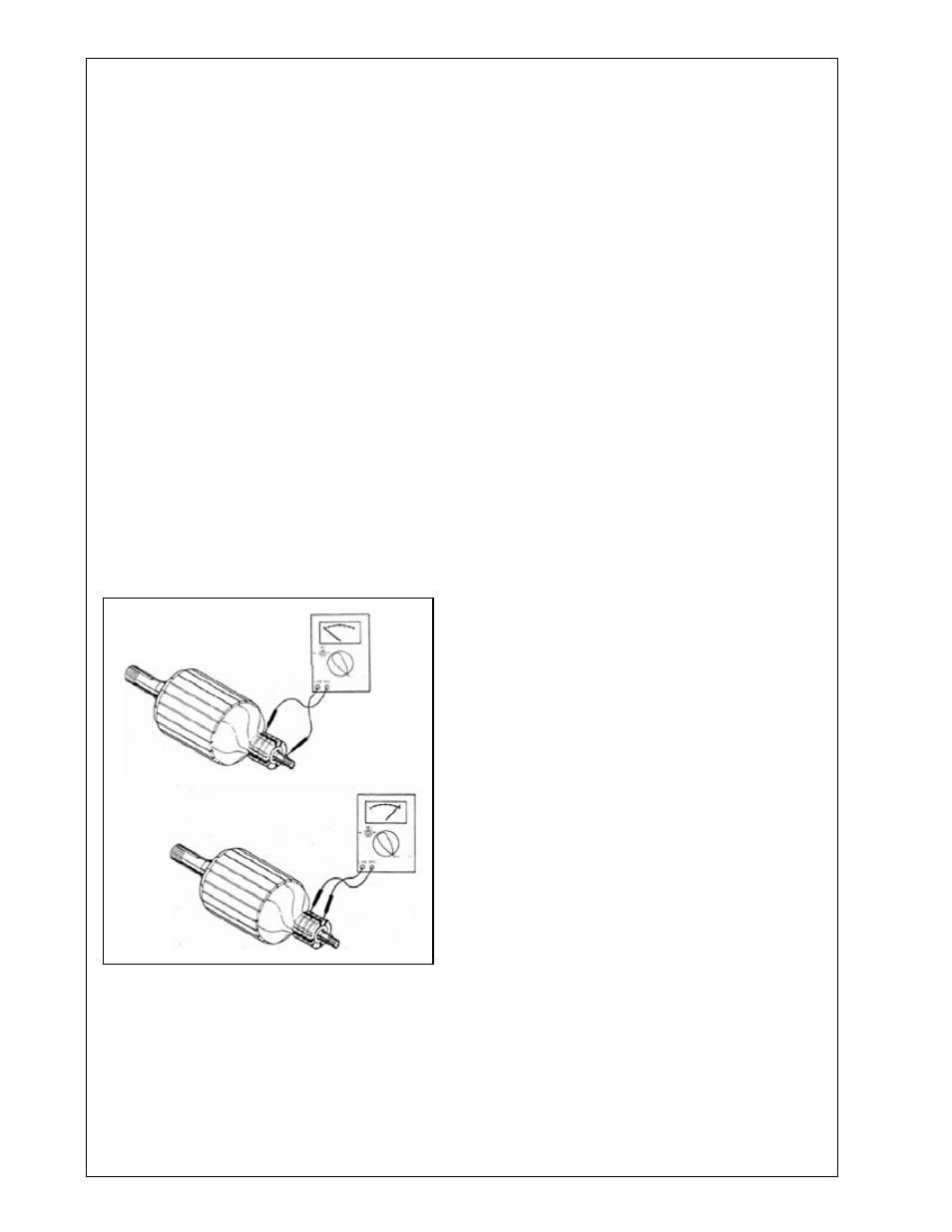
TESTING ARMATURE FOR OPENS AND
GROUNDS
. Remove all brushes.
2. Ground fault test. Set milti-meter to read high
resistance (mega-ohms). Holding one meter lead
against a clean spot on the armature shaft, touch
the other lead to each of the slip rings (one at a
time) while observing the meter. If meter indicates
continuity (any reading lower than one mega-
ohm), the armature is grounded. Dirt between the
slip rings and on the insulator surface can cause
grounding. If grounding was indicated, carefully
clean all dirt off the slip rings and their insulators
and then recheck it. Replace the armature if it is
grounded and unrepairable.
3. Testing for opens. Set meter to read low resis-
tance (R x ohms). Holding one meter lead on
the surface of slip ring # , touch the other lead to
surface of slip ring # 2 while observing the meter.
Meter should indicate continuity (low resistance
- less than one ohm is typical). If the meter indi-
cates an open
circuit (infinite resistance) part of the armature
winding is open. This may be caused by a re-
pairable defect in the connection at the slip ring,
however generally an open armature will have to
be replaced.
TESTING RECTIFIERS
The field excitation is supplied through full wave
bridge rectifier. This type of rectifier has four termi-
nals: two AC and a DC positive (+) and DC negative
(-). Nothing is connected to the DC negative (-) in
this generator.
A rectifier may be tested in the following manner:
1. Disconnect all leas from rectifier.
2. Connect the red ohmmeter lead to the positive
DC (+) terminal.
3. Connect the black lead to each of the AC termi-
nals in turn. Either a high or low resistance reading
will be obtained.
4. Reverse the meter lead, (black lead to the DC
positive (+) and red to the AC terminals, each in
turn. An opposite reading should be observed.
5. Check each terminal to the case. An open circuit
(very high resistance) reading should be observed.
If a battery powered test light is used follow the
same procedures described above. A good diode
element will allow current to pass to the light in the
test lamp when the lead are connected in the for-
ward direction.
6. If the rectifier fails any of the above tests, it
should be considered defective and replaced.