Winco 2FS Generators 2000 Watt Belt Drive User Manual
Page 7
7
2095-0
60706-230
MAINTENANCE
GENERAL
The main components of the generator are: field
frame, field coils, armature, brushes. brush holder
assembly, brackets, armature, and generator cooling
fan.
BRUSHES
Under ordinary circumstances brushes will operate
for thousands of hours without requiring replace-
ment. They should be inspected after the first
000 hours of operation, and after every 500 hours
of operation thereafter. Remove brushes one at
a time and check for length. Be sure that each
moves freely in the brush holder. Brushes should be
replaced when worn down to 3/8”. Always replace
brushes in complete sets, never singularly. When
replacing brushes be careful to reconnect the lead
wire properly. Poor contact or “skipping” between
brush and slip ring can be caused by oil and grit,
flint, or other hard contaminant substances on the
brushes, or by the brush not being properly shaped
to fit the slip rings.
Remedy these defects by cleaning the rings and
brushes and then fitting the brushes to the slip ring
curvature. Place #00 sandpaper under the brushes
with the abrasive side to the brushes, and work it
back and forth until the brushes are the same shape
as the slip rings.
SLIP RINGS
The continuous copper rings located at the end of
armature are the power collector rings or ‘slip rings’.
For proper generator output, the surface of these slip
rings must have a highly polished finish. Under sus-
tained use, it is advisable to check and occasionally
polish ring surfaces with a crocus cloth to maintain
the finish under normal conditions. This should not
be required more than once each thousand hours of
operation.
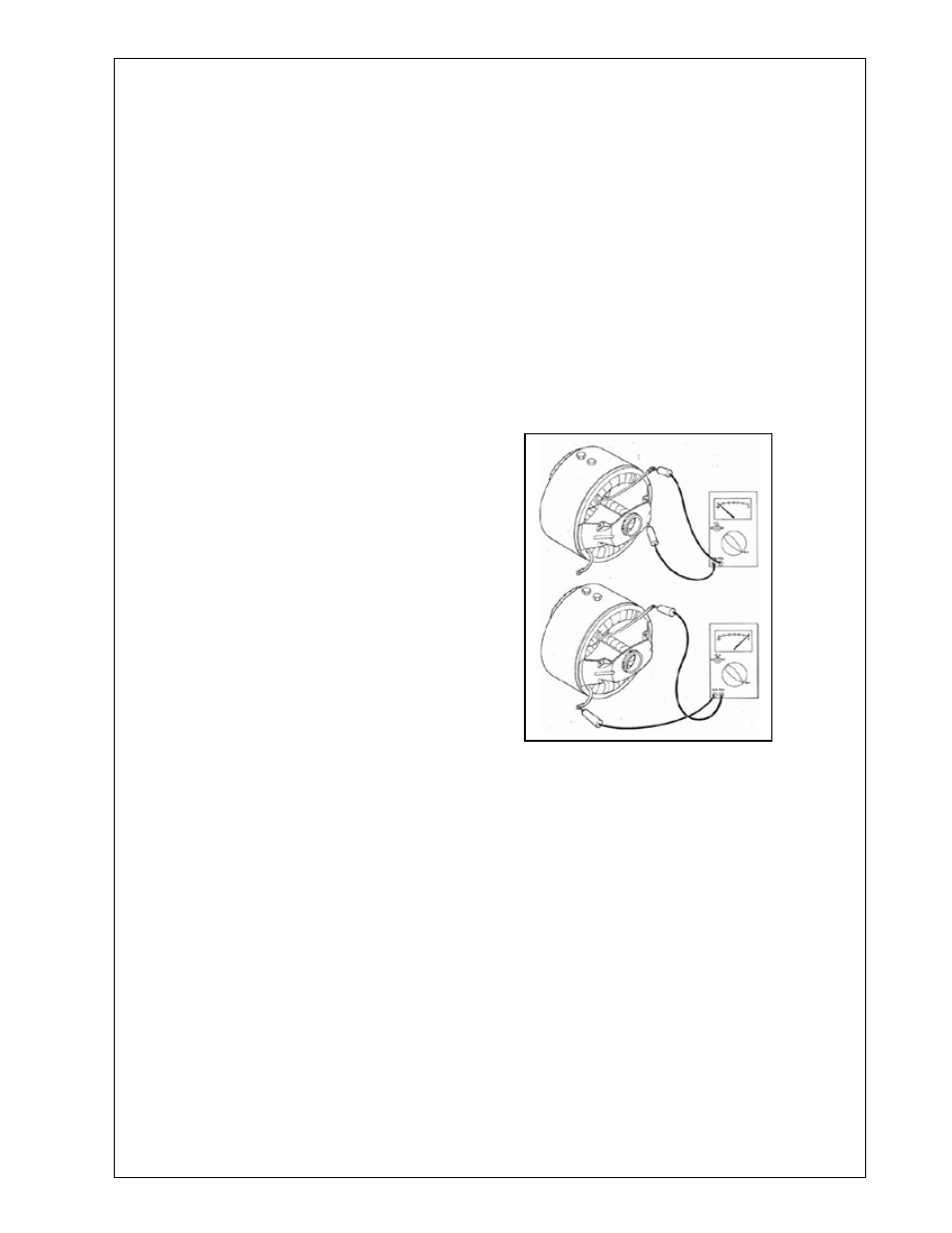
ELECTRICAL TESTING
TESTING COILS FOR OPENS AND GROUNDS
1. Disconnect field leads from rectifier.
2. Set multi-meter to read resistance, and connect
the meter leads to the field leads. If field is open,
meter will read infinite resistance (very high ohms),
repair or replace field if it is open. Typical resistance
for these fields varies from 12.8 to 14.1 ohms.
3. Leaving one meter lead connected to the field,
connect the other meter lead to the field shell. If
meter indicates continuity (any reading - should be
infinite resistance), the field is grounded and should
be repaired or replaced. To determine which of the
fields is grounded, cut the connector between the
two coils and retest to determine which coil has the
low resistance path.