The air brake charging system – Bendix Commercial Vehicle Systems TU-FLO 550 COMPRESSOR 6/08 User Manual
Page 4
4
brake charging system performance which may require
additional maintenance. Factors that add to the duty cycle
are: air suspension, additional air accessories, use of an
undersized compressor, frequent stops, excessive leakage
from fi ttings, connections, lines, chambers or valves, etc.
Refer to Table A in the Troubleshooting section for a guide
to various duty cycles and the consideration that must be
given to maintenance of other components.
COMPRESSOR INSTALLATION
While the original compressor installation is usually
completed by the vehicle manufacturer, conditions of
operation and maintenance may require additional
consideration. The following presents base guidelines.
DISCHARGE LINE
The discharge line allows the air, water-vapor and oil-vapor
mixture to cool between the compressor and air dryer or
reservoir. The typical size of a vehicle's discharge line,
(see column 2 of Table A in the Troubleshooting section)
assumes a compressor with a normal (less than 25%) duty
cycle, operating in a temperate climate. See Bendix and/or
other air dryer manufacturer guidelines as needed.
The discharge line must maintain a constant slope down
from the compressor to the air dryer inlet fi tting or reservoir
to avoid low points where ice may form and block the fl ow.
If, instead, ice blockages occur at the air dryer or reservoir
inlet, insulation may be added here, or if the inlet fi tting is
a typical 90 degree fi tting, it may be changed to a straight
or 45 degree fi tting. Shorter discharge line lengths or
insulation may be required in cold climates.
While not all compressors and charging systems are
equipped with a discharge line safety valve this component
is recommended. The discharge line safety valve is
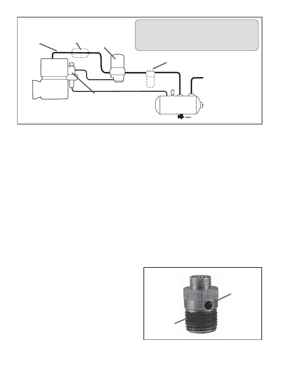
FIGURE 6A - SYSTEM DRAWING
FIGURE 6B - DISCHARGE LINE SAFETY VALVE
HOLE
THREAD
installed in the cylinder head (Tu-Flo
®
550/750) or close to
the compressor discharge port and protects against over
pressurizing the compressor in the event of a discharge
line freezeup.
DISCHARGE LINE TEMPERATURE
When the temperature of the compressed air that enters
the air dryer is within the normal range, the air dryer can
remove most of the charging system oil. If the temperature
of the compressed air is above the normal range, oil as
oil-vapor is able to pass through the air dryer and into the
air system. Larger diameter discharge lines and/or longer
discharge line lengths can help reduce the temperature.
The air dryer contains a fi lter that collects oil droplets, and
a desiccant bed that removes almost all of the remaining
water vapor. The compressed air is then passed to the air
brake service (supply) reservoir. The oil droplets and the
water collected are automatically purged when the governor
reaches its "cut-out" setting.
Air Dryer
Reservoir Drain
Service Reservoir
(Supply Reservoir)
Compressor
Governor
(Governor plus Synchro valve
for the Bendix
®
DuraFlo
™
596
Compressor)
Discharge
Line
Optional “Ping” Tank
Optional Bendix
®
PuraGuard QC
™
Oil Coalescing Filter
The Air Brake Charging System
supplies the
compressed air for the braking system as well as other air
accessories for the vehicle. The system usually consists
of an air compressor, governor, discharge line, air dryer,
and service reservoir.