American Dryer Corp. MLG-130DR (HSI) User Manual
Page 26
22
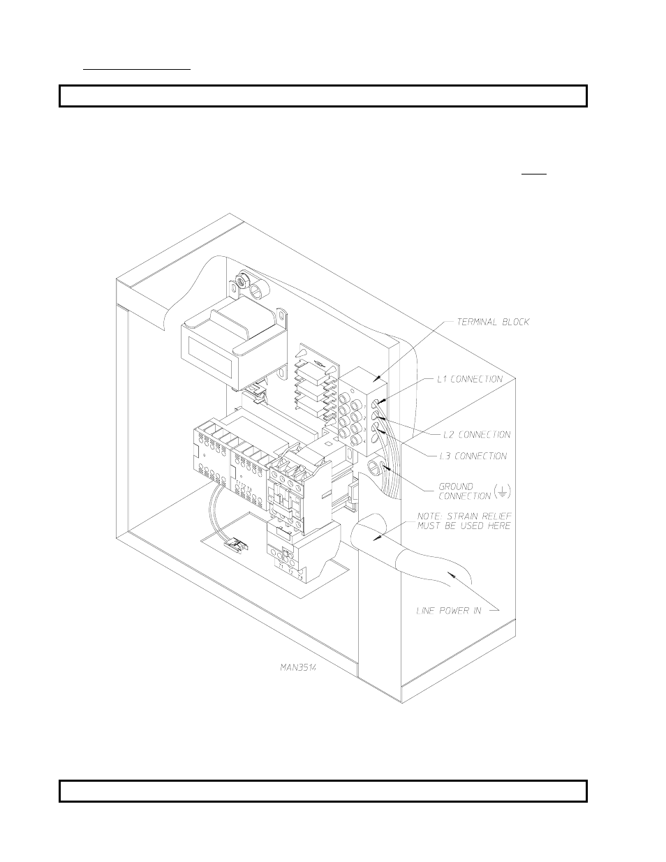
3. Electrical Connections
NOTE: A wire diagram is located in the front electrical control box for connection data.
The only electrical input connections to the dryer are the 3-phase (3ø) power leads (L1, L2, and L3),
GROUND, and in the case of 4 wire service, the NEUTRAL. Providing local codes permit, power connections
to the dryer can be made by use of a flexible underwriters laboratory list cord/pigtail (wire must conform
to ratings of the dryer), or the dryer can be hard wired directly to the service breaker. In ALL cases, a
strain relief must be used where the wire(s) enter the dryer electrical service (relay) box.
These electrical connections are made at the terminal block located in the electric service/relay box at the
rear, upper left hand corner of the dryer. To gain access into this service box, the service cover must be
removed.
NOTE: A CIRCUIT SERVING EACH DRYER MUST BE PROVIDED.
- SL2929 (8 pages)
- AD-15 Phase 7 (31 pages)
- ML-75DIII (65 pages)
- AD-236 (33 pages)
- AD-50V (61 pages)
- ML-96HS (38 pages)
- 75 lb (6 pages)
- SL2020 (8 pages)
- AD-758DV (52 pages)
- Aquatex AD-76 (36 pages)
- MDG-75 (66 pages)
- MLG31PCB (44 pages)
- AD-410 (72 pages)
- AD-75THS (49 pages)
- Direct Spark Ignition ADG-530DSi II (33 pages)
- MLG32PD3 (39 pages)
- ML-55 (52 pages)
- ML-96 (34 pages)
- ADG-410 (75 pages)
- ADG-320D (53 pages)
- Phase 7 Gas/Steam AD-464 (62 pages)
- AD-120ES (50 pages)
- Gas/Electric/Steam ML-55HS (56 pages)
- AD-840 (47 pages)
- MDG31 (26 pages)
- D20 (37 pages)
- Aquatex AD-52 (37 pages)
- Phase 7 D30 (39 pages)
- 30 lb. Stacked Models (26 pages)
- ADH-120 (46 pages)
- ML-96D (43 pages)
- Super AD-50 (54 pages)
- ML-122 (52 pages)
- SL31 (12 pages)
- Super AD-30 (63 pages)
- MDG30V (52 pages)
- AD-670 (60 pages)
- SL31AD-15 (72 pages)
- ADS-464 II (80 pages)
- ML-190 (42 pages)
- Heat Reclaimer AD-170HR (20 pages)
- 50 lb. Single Pocket MDG50V (52 pages)
- 24 VAC Phase 5 AD-330 (40 pages)
- D75 (42 pages)