Dwyer 634ES User Manual
Page 3
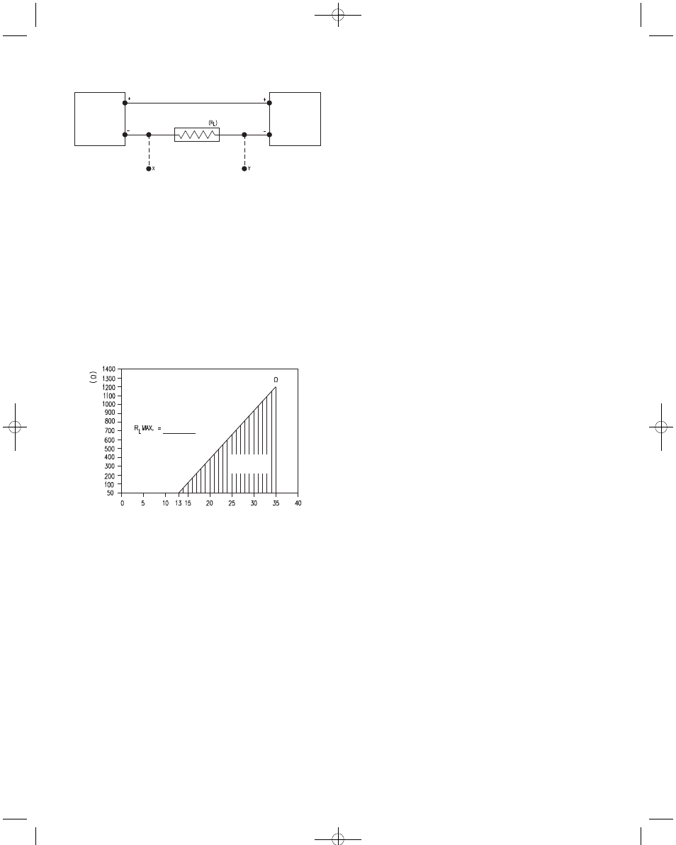
FIG. B
Series 634ES Transmitters can be used with receivers requiring 1-5 volt
input rather than 4-20 mA. If the receiver requires a 1-5 volt input, insert a
250 ohm, 2 watt resistor in series with the current loop but in parallel with
the receiver input. Referring to Figure B, R
L
becomes the 250 ohm resis-
tor and points X and Y are connected to the receiver input, point X being
positive (+) and point Y negative (-) or ground. The resistor should be
connected at the panel end of the transmitter current loop close to the
receiver input to take advantage of the immunity of the current loop to
electrical noise pickup. Most electronic component distributors stock a
249 Ω, 2 watt, ± 1% tolerance metal film resistor which is adequate for
this application.
634ES
PRESSURE
TRANSMITTER
RECEIVER
SEE FIG. C
POWER
SUPPLY
12-35 VDC
OPERATING
REGION
MAXIMUM VALUE (1100 )
T
O
T
AL RECEIVER RESIST
ANCE
Vps-12.3
20mA DC
WIRE LENGTH - The maximum length of wire connecting transmitter
and receiver is a function of wire size and receiver resistance. Wiring
should not contribute more than 10% of receiver resistance to total loop
resistance. For extremely long runs (over 1000 feet) choose receivers
with higher resistances to minimize size and costs of connecting leads.
When wiring length is under 100 feet, lead wire as small as 22 AWG can
be used.
PRESSURE RANGING - Each Series 634ES Transmitter is factory-cal-
ibrated to the range given in the model number chart. However, special
calibration is also available. If this is the case, the transmitter will be so
marked. For purposes of clarification in these instructions, range is
defined as that pressure which, applied to the transmitter, produces 20
mA of current in the loop. Zero pressure is always assumed to be 4 mA.
If a transmitter pressure range other than that supplied is required, fol-
low the re-ranging procedure described on Pg. 4.
FIG. C
E-69ES:E-69ES (634ES)-4.0 9/24/09 11:49 AM Page 3