Dwyer 634ES User Manual
Page 2
INSTALLATION
LOCATION: Select a location where temperature of the unit will be
between 20°F and 120°F. Distance from the receiver is limited only by
total loop resistance. See “Electrical Connections.” The tube feeding the
pressure to the instrument can be run practically any length required, but
long lengths will slightly increase response time. Avoid surfaces with
excessive vibration.
POSITION: A vertical position is recommended, as all stocked models
are spanned and zeroed at the factory in this position. They can be used
at other angles, but final spanning and zeroing must be done while trans-
mitter is in the alternative position.
PRESSURE CONNECTIONS: A single pressure connection is provided
at the bottom of the transmitter housing. It has1/4” female NPT and 1/2”
male NPT threads. Attach positive pressure to this port.
MOUNTING: The Series 634ES Transmitter can be mounted three ways:
(A) Supported directly by pipe providing pressure.
(B) Attached to a mounting surface with 10-32 x 1/4” machine screws
(included). The machine screws are installed through the mounting sur-
face into tapped holes on back of unit.
(C) Mounted with “Z” brackets (included). Attach “Z” brackets to tapped
holes on back of unit and fasten to front of mounting surface.
ELECTRICAL CONNECTIONS
CAUTION: DO NOT EXCEED SPECIFIED SUPPLY VOLTAGE RAT-
INGS. PERMANENT DAMAGE NOT COVERED BY WARRANTY WILL
RESULT. THIS UNIT IS NOT DESIGNED FOR AC VOLTAGE OPERA-
TION.
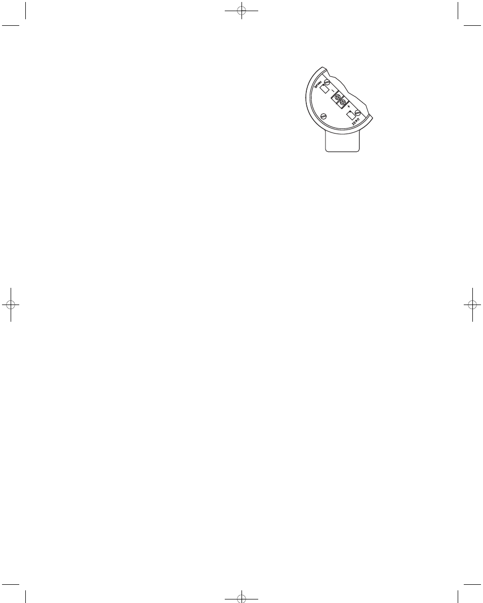
Electrical connections to the Series 634ES Transmitter are made inside
the enclosure. Remove the cover, feed stripped and tinned leads through
the conduit opening and connect to terminal block screws marked + and
-. See Figure A for locations of terminal block, span and zero adjust
potentiometers. See Figure B (Pg. 3) for schematic diagram.
FIG. A
An external power supply delivering 12.3 to 35 VDC with minimum cur-
rent capability of 40 mA must be used to power the control loop in which
the Series 634ES Transmitter is connected. See Figure B for connection
of the power supply, transmitter and receiver.
The range of appropriate receiver load resistance (R
L
) for the power sup-
ply voltage available is given by the formula and graph in Figure C on Pg.
3.
Shielded 2-wire cable is recommended for control loop wiring, and the
cable shielding may be grounded if desired. Note also that the receiver
may be connected in either the negative or positive side of the loop,
whichever is most convenient.
Should polarity of the transmitter or receiver inadvertently become
reversed, the loop will not function properly, but no damage will be done
to the transmitter.
E-69ES:E-69ES (634ES)-4.0 9/24/09 11:49 AM Page 2