Figure 3. a4a8 component location/wiring, E 3 for – KEPCO Kit 219-0549, Transition Circuit Kit BOP-1KW Model 26600 User Manual
Page 4
4
228-1745 REV 2
071812
KEPCO, INC. 131-38 SANFORD AVENUE FLUSHING, NY. 11355 U.S.A. TEL (718) 461-7000 FAX (718) 767-1102
http://www.kepcopower.com email: [email protected]
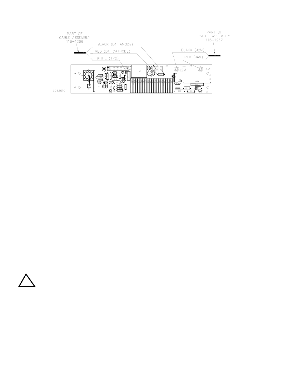
FIGURE 3. A4A8 COMPONENT LOCATION/WIRING
4. Install the 5-pin cable assembly (P/N 118-1265) on Transition Circuit A7A3J1 (see Figure 1) of the PCB. Route
the cables as shown by Figure 6. This cable assembly has a 5-pin connector with five (5) unterminated wires.
Determine the needed length, cut the wire and remove the insulated sleeving (approximately 0.15"), then sol-
der each wire to the indicated point of assembly A2A5 (see Figure 4 for location of wire attachment points and
Figure 6 for cable routing):
• white/yellow wire to junction of A2A5R70 and U11, pin 8
• white/blue wire to A2A5TP1
• black wire to A2A5TP2
• red wire to A2A5TP9
• white wire to A2A5TP8
5. To gain access to the components of A4A3 in order to replace R58, R59 and R70, first remove A4A3 from the
chassis as follows:
a. At top of A4A3 disconnect nine cables from J1 through J9 of A4A3 (Figure 5).
b. Remove four screws attaching A4 assembly to the chassis.
c. Remove five screws and five washers attaching A4A3 board to A4A1 board and remove A4A3 board.
6. Unsolder and remove the following three resistors from A4A3 and replace with the resistors supplied as fol-
lows (see Figure 5 for location of A4A3 components):
• Install and solder replacement R59 supplied: P/N 115-2597 (150K Ohms, 1%, 0.125W)
• Install and solder replacement R58 and R70 supplied: P/N 115-2809 (200K Ohms, 1%, 0.25W)
7. Reinstall A4A3 by following the reverse of step 5 above.
8. Perform visual inspection of transition circuit installation.
CAUTION: After installing all components and wiring as described above, perform the following
checklist to verify that installation has been done correctly.
• Verify that cable wires are connected properly and to the correct termination
• Check for unintentional short-circuits between the wire connections and adjacent components, pads and
traces.
• Use an ohmmeter to verify that the Transition Circuit heatsink is isolated (more than 1Megohm resistance)
from the BOP chassis.
• Verify that the Transition Circuit is securely attached to the BOP chassis.
• Verify that the Transition circuit cables are clear of the Output Module (A2) Fan and Auxiliary Power Supply
(A5).
!