Installation, Mount the back panel, Description of the processor board – Chamberlain TAC1 User Manual
Page 4
4
1
9
10
6
5
12
11
2
13
1
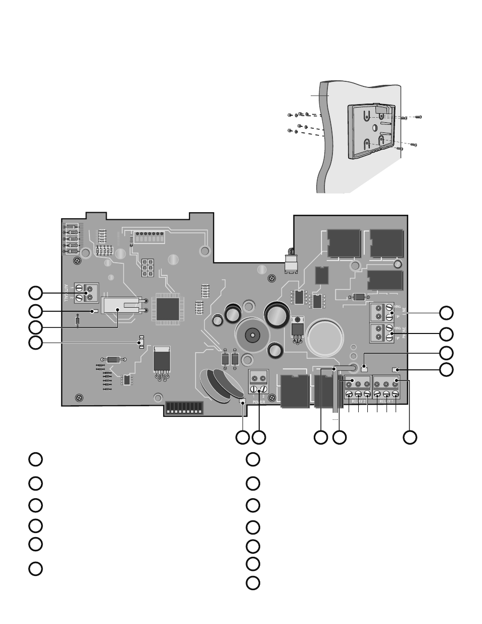
Autocall Input:
Connector for accessory device to trigger
home dialing.
2
Power Connector: 12 Volt AC power input.
8
Ground Wire: Wire must be connected to positive earth
ground. See Earth Ground Rod.
7
Tamper Switch
5
Phone Output: Telephone return connection to home or
office phones.
6
Line Input: Telephone input connection from “Telco” service
provider.
4
Relay 1 Output: Form “C” primary control relay.
12
Relay 1 (Primary) Output Status LED
13
Relay 2 (Secondary) Output Status LED
10
Voice Data Send Status LED
9
Status LED
11
Power Status LED
8
Choose the mounting location for the unit. Remove the back panel from
the unit by pulling the top of the panel out of the unit. Mount the panel
to a solid surface or post (hardware not provided) with the top of the
panel up.
IMPORTANT NOTE: Both the back panel and TAC1 unit must be oriented
and mounted in the upright position as shown at right and on the
installation warning label. Failure to correctly mount the panel and unit
may cause damage to the board during installation.
Mounting
Surface
Top of Back Panel
Bottom of Back Panel
INSTALLATION
>> MOUNT THE BACK PANEL AND OVERVIEW OF THE PROCESSOR BOARD
DESCRIPTION OF THE PROCESSOR BOARD
MOUNT THE BACK PANEL
3
4
7
3
Relay 2 Output: Form “C” secondary control relay.
NC
NC
NO
NO
COM
COM