Aeromotive 17158 - COBRA JET COMPLETE FUEL SYSTEM User Manual
Page 6
2-7. Disconnect the electrical connector at each injector, making note of the location of each. Also disconnect the fuel
pressure sensor located on the passenger side fuel rail.
2-8. Disconnect the supply line from the OEM fuel rails. This line is attached by a special quick disconnect fitting which
does not require a special tool for removal. Place clean shop towels around the open fuel line to catch any gasoline
that may drip out and to prevent any dirt from entering the fuel lines.
2-9. Remove the 4 bolts that attach the fuel rail to the lower intake.
2-10. Place clean shop towels around the injectors to catch any gasoline that may be spilled during their removal.
Remove the injectors from the manifold by gently pulling upward on the fuel rail / injector assembly. Keep all injectors
connected to the fuel rails. If an injector does pull out of the fuel rail, it may spill a large amount of fuel.
2-11. Carefully remove the fuel injectors from the OEM fuel rail.
2-12. Remove the old o-rings from the fuel injectors, inspect the injectors for any dirt or debris and clean if needed. It is
suggested that the old o-rings be replaced, contact your local Ford parts dept.
2-13. Coat the fuel injector o-rings with a light oil to ease installation.
2-14. Carefully install the fuel injector o-rings on the injectors.
2-15. Place a thin coat of light oil in the fuel rail fuel injector bores and in the lower intake manifold injector bores to help
prevent cutting the o-rings during installation.
2-16. Carefully place the fuel injectors in the fuel rails. Position the electrical connector on each fuel injector on the
opposite side of the mounting bracket.
2-17. Install both fuel rails, being careful not to cut any of the o-rings during installation.
2-18. Find suitable place in the vehicle’s engine compartment to mount the Aeromotive regulator, typically on the
passenger side inner fender or shock tower. Using the supplied mounting bracket as a template, mark the bracket
mounting holes and drill to accept a #10 screw.
2-19. With the bracket attached to the regulator, mount the bracket and regulator to the vehicle using two #10 screws,
nuts and lock washers.
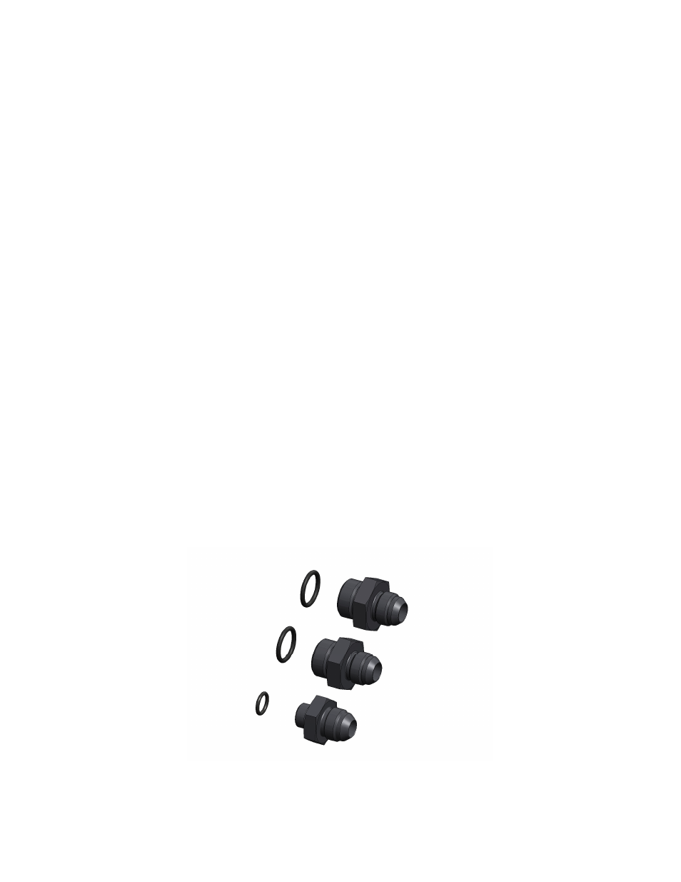
2-20. Install one AN-10 o-ring on each of the two AN-10 to AN-08 union fittings (15610) and one AN-6 o-ring on the AN-6
to AN-08 fitting (15649).
2-21. Thread the side of the AN-10 cutoff’s with the o-ring into each of the two AN-10 ports on the regulator. Also do the
same for the AN-6 cutoff fitting in the return port on the bottom of the regulator.