Pam8620, Application information – Diodes PAM8620 User Manual
Page 8
PAM8620
Document number: DSxxxxx Rev. 1 - 0
8 of 13
June 2013
© Diodes Incorporated
PAM8620
A Product Line of
Diodes Incorporated
Application Information
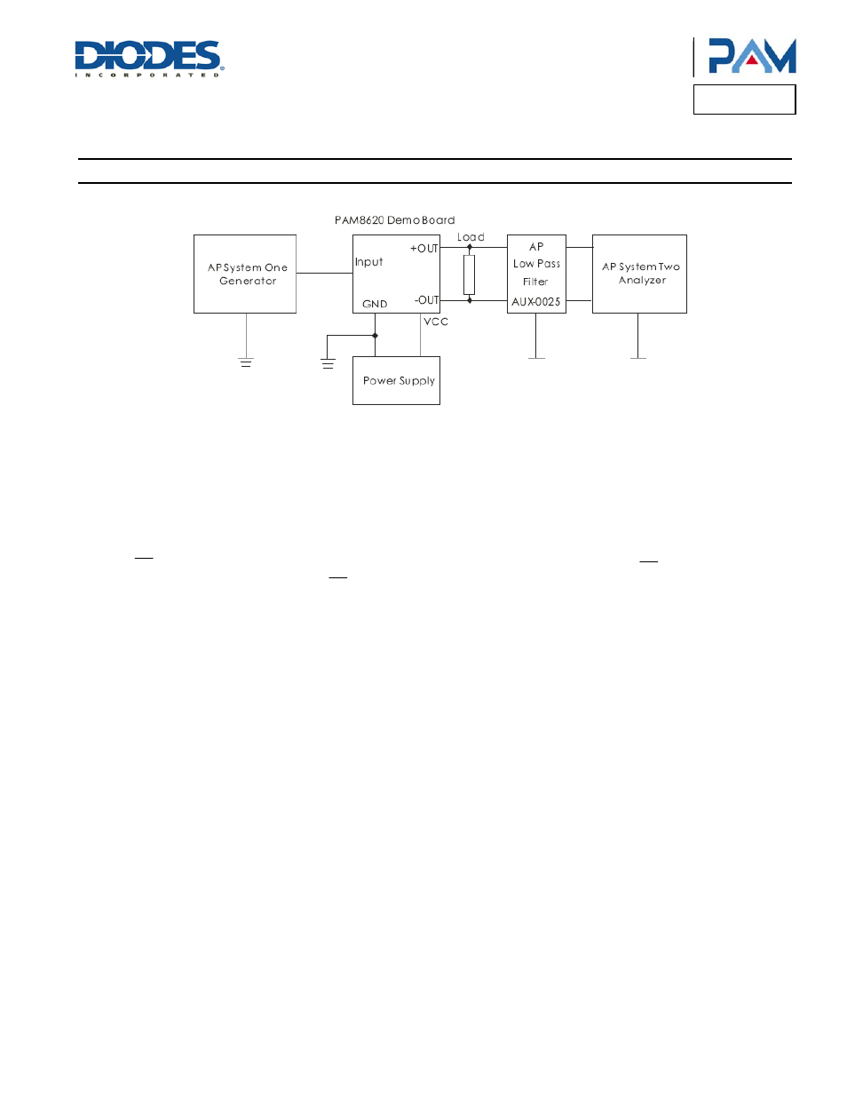
Test Setup for Performance Testing
Notes:
1. The AP AUX-0025 low pass filter is necessary for class-D amplifier measurement with AP analyzer.
2. Two 22µH inductors are used in series with load resistor to emulate the small speaker for efficiency measurement.
MUTE Operation
The MUTE pin is an input for controlling the output state of the PAM8620. A logic high on this pin disables the outputs and low enables the
outputs. This pin may be used as a quick disable or enable of the outputs without a volume fade.
Shutdown Operation
The PAM8620 employs a shutdown operation mode to reduce supply current to the absolute minimum level during periods of non-use to save
power. The SD input terminal should be held high during normal operation when the amplifier is in use. Pulling SD low causes the outputs to
mute and the amplifier to enter a low-current state. SD should never be left unconnected to prevent the amplifier from unpredictable operation.
For the best power-off pop performance, the amplifier should be set in shutdown mode prior to removing the power supply voltage.
Internal 2.5V Bias Generator Capacitor Selection
The internal 2.5V bias generator (V2P5) provides the internal bias for the preamplifier stage. The external input capacitors and this internal
reference allow the inputs to be biased within the optimal common-mode range of the input preamplifiers.
The selection of the capacitor value on the V2P5 terminal is critical for achieving the best device performance. During startup or recovery from
shutdown state, the V2P5 capacitor determines the rate at which the amplifier starts up. When the voltage on the V2P5 capacitor equals 0.75 x
V2P5, or 75% of its final value, the device turns on and the class-D outputs start switching. The startup time is not critical for the best de-pop
performance since any heard pop sound is the result of the class-D output switching-on other than that of the startup time. However, at least a
0.47µF capacitor is recommended for the V2P5 capacitor.
Another function of the V2P5 capacitor is to filter high frequency noise on the internal 2.5V bias generator.
Power Supply Decoupling, C
S
The PAM8620 is a high-performance CMOS audio amplifier that requires adequate power supply decoupling to ensure the output total harmonic
distortion (THD) as low as possible. Power supply decoupling also prevents oscillations caused by long lead between the amplifier and the
speaker. The optimum decoupling is achieved by using two capacitors of different types that target different types of noise on the power supply
leads. For higher frequency transients, spikes, or digital hash on the line, a good low equivalent-series resistance (ESR) ceramic capacitor,
typically 1µF, is recommended, placing as close as possible to the device’s VCC lead. To filter lower frequency noises, a large aluminum
electrolytic capacitor of 10µF or greater is recommended, placing near the audio power amplifier. The 10µF capacitor also serves as a local
storage capacitor for supplying current during large signal transients on the amplifier outputs.
BSN and BSP Capacitors
The full H-bridge output stages use NMOS transistors only. They therefore require bootstrap capacitors for the high side of each output to turn
on correctly. A at least 220nF ceramic capacitor, rated for at least 25V, must be connected from each output to its corresponding bootstrap input.
Specifically, one 220nF capacitor must be connected from xOUTP to xBSP, and another 220nF capacitor from xOUTN to xBSN. It is
recommended to use 1µF BST capacitor to replace 220nF or lower than 100Hz applications.