Pam8620, Application information – Diodes PAM8620 User Manual
Page 10
PAM8620
Document number: DSxxxxx Rev. 1 - 0
10 of 13
June 2013
© Diodes Incorporated
PAM8620
A Product Line of
Diodes Incorporated
Application Information
(cont.)
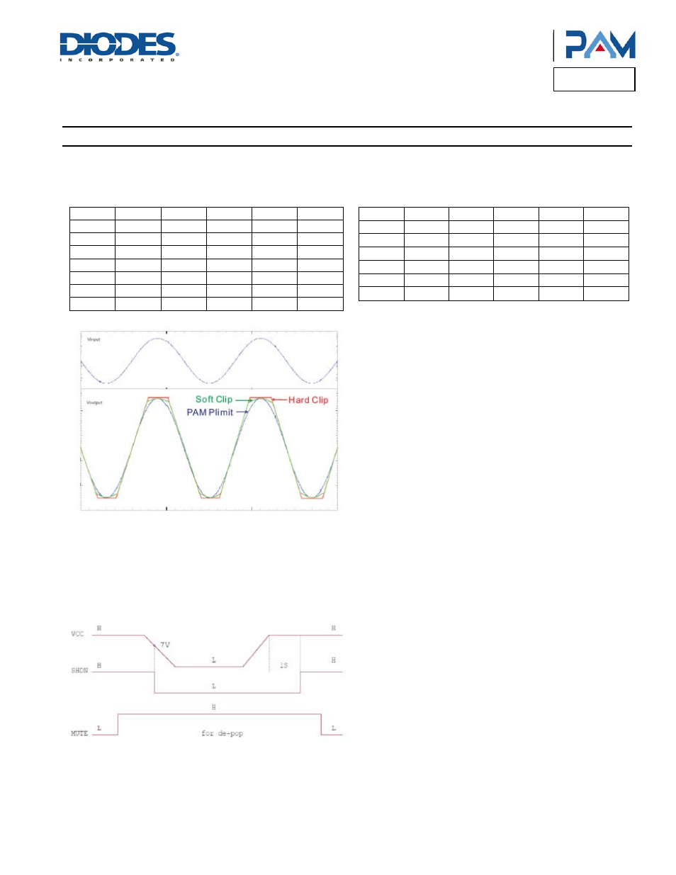
Power Limit
(cont.)
The output power vs PL pin resistor value as below.
V
CC
= 24V, R
LOAD
= 8•
V
CC
= 12V, R
LOAD
= 8•
R(• )
PL(V)
PL(W)
R(• )
PL(V)
PL(W)
56K
0.62
3.2
110K
1.08
9.6
62K
0.68
3.8
120K
1.15
11.0
68K
0.73
4.4
130K
1.23
12.4
75K
0.79
5.2
150K
1.36
15.5
82K
0.86
6.1
160K
1.43
17.0
91K
0.93
7.1
180K
1.55
19.9
100K
1.00
8.2
200K
1.66
22.9
R(• )
PL(V)
PL(W)
R(• )
PL(V)
PL(W)
56
0.61
3.1
100K
0.99
8.1
62
0.67
3.7
110K
1.07
9.0
68
0.73
4.3
120K
1.115
9.6
75
0.79
5.1
130K
1.22
10.0
82
0.85
6.0
140K
1.36
10.7
91
0.92
7.0
—
—
—
Power Up/Down Sequence
The PAM8620 employs a shutdown operation mode to reduce supply current to the absolute minimum level during periods of non-use to save
power. The SD input terminal should be held high during normal operation when the amplifier is in use. Pulling SD low causes the outputs to
mute and the amplifier to enter a low-current state. SD should never be left unconnected to prevent the amplifier from unpredictable operation.
Suggest PL starting voltage is greater than 5V.
Start-up /power down sequencer recommended.