Pam2805, Application information, Ordering information – Diodes PAM2805 User Manual
Page 7: Marking information
PAM2805
Document number: DSxxxxx Rev. 1 - 0
7 of 9
July 2013
© Diodes Incorporated
PAM2805
A Product Line of
Diodes Incorporated
Application Information
PCB Layout Guidelines
As for all switching power supplies, the layout and components placement of the PAM2805 is an important step in the design; especially at high
peak currents and high switching frequencies.
The input capacitor and output capacitor should be placed respectively as close as possible to the input pin and output pin of the IC; the inductor
and schottky diode should be placed as close as possible to the switch pin by using wide and short traces for the main current path; the current
sense resistor should be placed as close as possible between the ground pin and feedback pin.
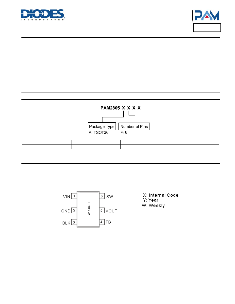
Ordering Information
Part Number
Marking
Package Type
Standard Package
PAM2805AF ECXYW
TSOT26
3000
Units/Tape&Reel
Marking Information
Top View
TSOT26