Ap8803, Application information – Diodes AP8803 User Manual
Page 8
AP8803
Document number: DS31970 Rev. 5 - 2
8 of 10
August 2012
© Diodes Incorporated
AP8803
Application Information
(cont.)
Fault Condition Operation
The AP8803 has by default open LED protection. If the LEDs should become open circuit the AP8803 will stop oscillating; the SET pin will rise
to V
IN
and the SW pin will then fall to GND. No excessive voltages will be seen by the AP8803.
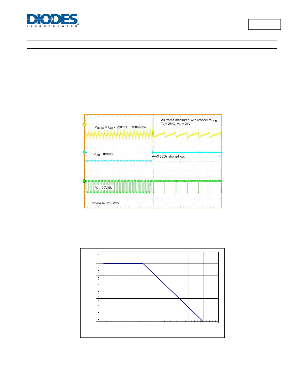
If the LEDs should become shorted together the AP8803 will continue to switch however the duty cycle at which it will operate will change
dramatically and the switching frequency will most likely decrease. The on-time of the internal power MOSFET switch will be significantly
reduced because almost all of the input voltage is now developed across the inductor. The off-time will be significantly increased because the
reverse voltage across the inductor is now just the Schottky diode voltage (See Figure 7) causing a much slower decay in inductor current.
During this condition the inductor current will remain within its controlled levels and so no excessive heat will be generated within the AP8803.
Figure 7 Switching Characteristics (normal open to short LED chain)
Thermal Considerations
The graph below in Figure 8, gives details for power dissipation derating. This assumes the device to be mounted on a 25 x 25mm PCB with
1oz copper standing in still air.
0
0.2
0.4
0.6
0.8
1
1.2
-50
-25
0
25
50
75
100
125
150
Ambient Temperature (°C)
P
owe
r d
is
s
ipa
ti
on
(W
)
Figure 8 Power Dissipation Derating Curve
The maximum power dissipation is affected by PCB area and the area of copper associated with the LX pin as well as other components on the
PCB generating heat – such as the inductor, capacitor or rectifiers.