Ap8803, Application information – Diodes AP8803 User Manual
Page 5
AP8803
Document number: DS31970 Rev. 5 - 2
5 of 10
August 2012
© Diodes Incorporated
AP8803
Application Information
(cont.)
Inductor Selection
A 33
μH inductor (or higher) is recommended for most AP8803 applications with input voltage at 24V.
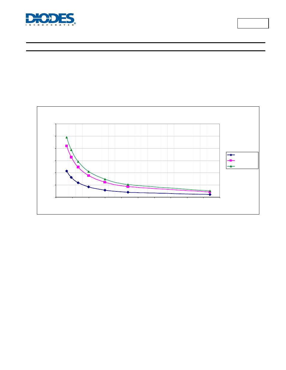
Figure 3 displays the resulting switching frequency varying the main circuit parameters: Supply voltage, inductor value and number of LEDs to
be driven.
In particular, the graph in Figure 3 gives values of nominal switching frequency for several values of inductors (L1) in the typical application
circuit shown on Figure 1, for different input voltages and load condition. It can be used to determine the inductor value based on the desired
switching frequency and the input and load conditions.
Switching Frequency @ I
LED
=1A
33
47
68
220
470
100
150
68
33
47
220
100
150
0
100
200
300
400
500
600
0
50
100
150
200
250
300
350
400
450
500
Inductor Value [uH]
Fr
eque
ncy
[k
H
z
]
12V - 1 LED
24V - 3 LEDs
30V - 5 LEDs
Figure 3 Switching Frequency vs. Supply Voltage, Inductor, and Number of LEDs
Capacitor Selection
The small size of ceramic capacitors makes them ideal for AP8803 applications. X5R and X7R types are recommended because they retain
their capacitance over wider voltage and temperature ranges than other types such as Z5U. A 2.2
μF input capacitor is sufficient for most
intended applications of AP8803.
Diode Selection
Schottky diodes, e.g. B240 or DFLS240L in the proprietary PowerDI123 package, with their low forward voltage drop and fast reverse recovery,
are the ideal choice for AP8803 applications.
In addition, Super Barrier Rectifier devices (as SBR2A40P1) can be used for their enhanced thermal performances.