Bsn20 new prod uc t, Bsn20 – Diodes BSN20 User Manual
Page 3
BSN20
Document number: DS31898 Rev. 8 - 2
3 of 6
www.diodes.com
September 2013
© Diodes Incorporated
BSN20
NEW PROD
UC
T
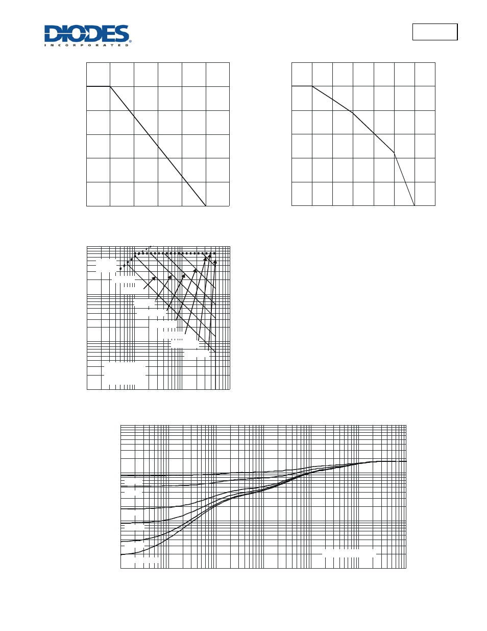
Fig 1. Normalized Total Power Dissipation
as a Function of Solder Point Temperature
0
20
40
60
80
100
120
25
50
75
100
125
150
175
T , SOLDER POINT TEMPERATURE (°C)
S
P
, PO
W
E
R DI
SSI
P
A
T
IO
N
(
%
)
D
0
20
40
60
80
100
120
I,
N
O
R
MA
L
IZ
E
D
C
O
N
T
IN
U
O
U
S
C
U
R
R
EN
T
(%
)
DE
R
Fig 2. Normalized Continuous Current
vs. Solder Point Temperature
0
50
75
100
125
150
175
T , SOLDER POINT TEMPERATURE (°C)
S
25
Fig. 3 SOA, Safe Operation Area
0.1
1
10
100
V
, DRAIN-SOURE VOLTAGE (V)
DS
R
ds(on)
Limited
I,
D
R
AI
N
C
U
R
R
EN
T
(A
)
D
0.001
0.01
0.1
1
T
= 150°C
T = 25°C
Single Pulse
J(MAX)
A
P
= 10s
W
P
= DC
W
P
= 1s
W
P
= 100ms
W
P
= 10ms
W
P
= 1ms
W
P
= 100µs
W
P
= 10µs
W
Z,
T
R
AN
S
IE
N
T
T
H
E
R
MA
L
R
ES
IS
T
AN
C
E (
°C
/W
)
th
(j
-s
p
)
1
10
100
1,000
0.00001
0.0001
0.001
0.01
0.1
1
10
Fig. 4 Transient Thermal Response
t , PULSE DURATION TIME (s)
1
D = 0.5
D = 0.3
D = 0.1
D = 0.05
D = 0.02
D = Single Pulse
Duty Cycle, D = t /t
1 2
- PDS3200 (5 pages)
- PDS340 (5 pages)
- PDS340Q (5 pages)
- PDS360 (5 pages)
- PDS360Q (5 pages)
- PDS4150 (4 pages)
- PDS3100Q (5 pages)
- PDS3100 (5 pages)
- PDS1240CTL (5 pages)
- PDS1045 (5 pages)
- PDS1040L (5 pages)
- PDS1040CTL (5 pages)
- PDS1040 (5 pages)
- PD3S230L (5 pages)
- PD3S230H (3 pages)
- PDS5100Q (5 pages)
- PDS835L (5 pages)
- PDS760 (5 pages)
- PDS560 (5 pages)
- PDS540 (5 pages)
- PDS5100H (5 pages)
- PDS5100 (5 pages)
- PDS4200H (6 pages)
- SBL3060CTP (4 pages)
- SBL30L30CT (3 pages)
- SBL3045CTP (4 pages)
- SBL3040CTP (4 pages)
- SBL2060CTP (4 pages)
- SBL2030CT - SBL2060CT (3 pages)
- SBL2045CTP (4 pages)
- SBL1060CTP (4 pages)
- SBL1040CTP (4 pages)
- SBG3030CT - SBG3045CT (5 pages)
- SB520 - SB560 (3 pages)
- SB370 - SB3100 (3 pages)
- SB320 - SB360 (3 pages)
- SBR10U100CT (5 pages)
- SBR10U150CT (5 pages)
- SBR10A45SP5 (5 pages)
- SBR1060CT (5 pages)
- SBR1045SP5 (5 pages)
- SBR1045SD1 (4 pages)
- SBR1045D1 (5 pages)
- SBR1045CTL (4 pages)
- SBR1040CT (5 pages)