Zhb6792, Thermal characteristics, Transient thermal resistance – Diodes ZHB6792 User Manual
Page 2: Derating curve
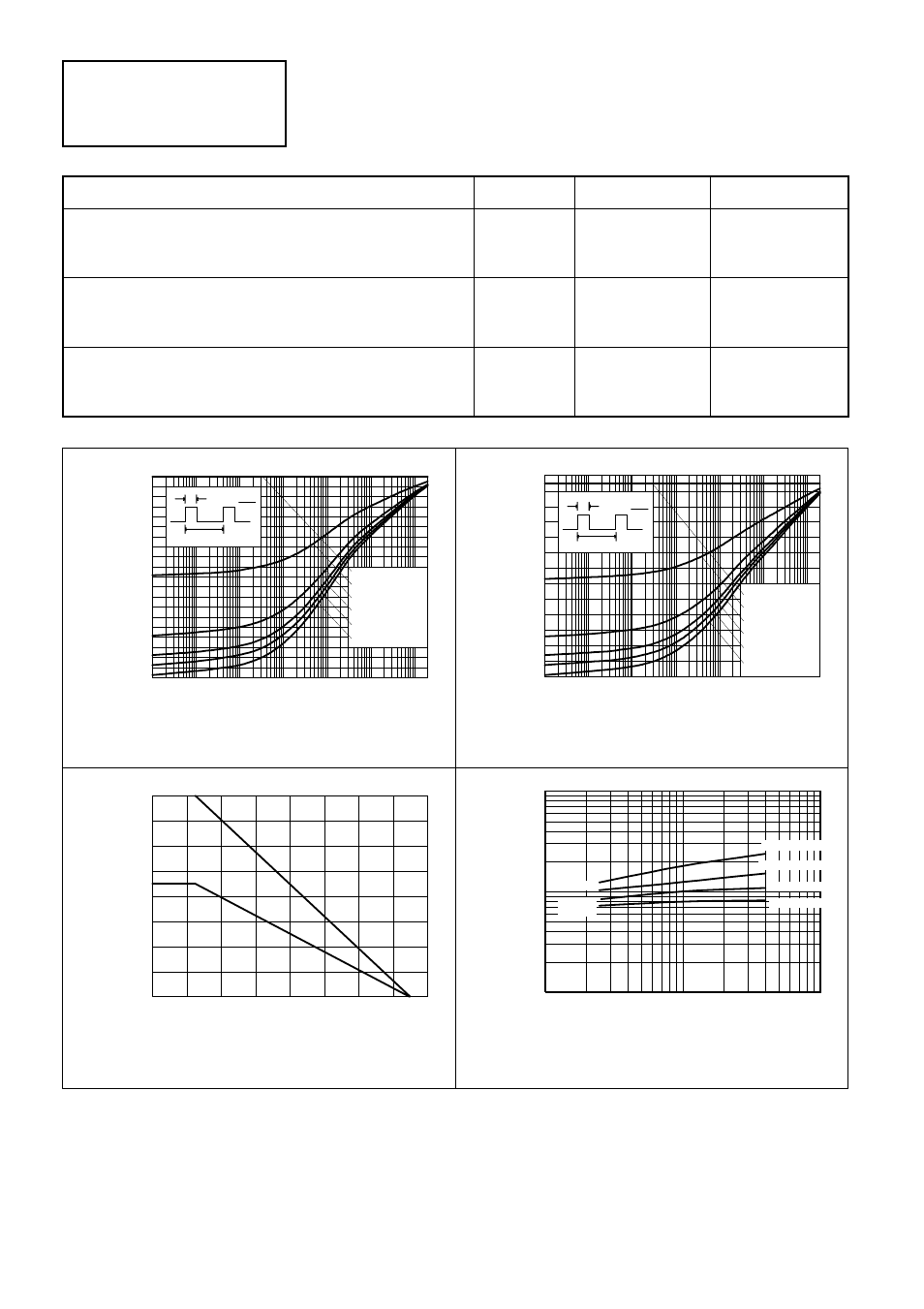
THERMAL CHARACTERISTICS
PARAMETER
SYMBOL
VALUE
UNIT
Total Power Dissipation at T
amb
= 25°C*
Any single transistor “on”
Q1 and Q3 “on” or Q2 and Q4 “on” equally
P
tot
1.25
2
W
W
Derate above 25°C*
Any single transistor “on”
Q1 and Q3 “on” or Q2 and Q4 “on” equally
10
16
mW/ °C
mW/ °C
Thermal Resistance - Junction to Ambient*
Any single transistor “on”
Q1 and Q3 “on” or Q2 and Q4 “on” equally
100
62.5
°C/ W
°C/ W
ZHB6792
100us
Pulse Width
Transient Thermal Resistance
0
Thermal
Resist
ance (°C/
W)
D=1
D=0.2
D=0.1
D=0.05
D=0.5
Single Pulse
D=t1
tP
t1
tP
1ms
10ms 100ms
1s
10s
100s
20
40
60
80
100
Therm
al Resista
nce (°C
/W)
Single Pulse
Transient Thermal Resistance
Pulse Width
t1
1ms
100us
0
10ms
tP
D=t1
tP
1s
100ms
D=0.2
D=0.05
D=0.1
10s
D=0.5
D=1
100s
10
20
30
40
50
60
T - Temperature (°C)
M
a
x P
owe
r
Diss
ip
a
ti
o
n - (W
att
s)
0
0.5
0
20
1.5
1.0
2.0
Sing
le
Derating curve
40
60
80
100
140
120
160
Du
al
Single Transistor "On"
Q1 and Q3 or Q2 and Q4 "On"
Pd v Pcb Area Comparison
P
o
w
e
r D
issapa
ti
on
(W)
0.1
0.1
10
Pcb Area (inches squared)
1
10
1
Dual Transistors †
Single Transistor
Dual Transistors †
Single Transistor
Full Copper
Minimum
Copper
* The power which can be dissipated assuming the device is mounted in a typical manner on a PCB
with copper equal to 2 inches square.
†"Two devices on" is the standard operating condition for the bridge. Eg. opposing NPN/PNP pairs
rurned on.