Rs-422/485 serial connections, Figure 17 - rs-422/485 db-9 pin designations, Table 3 - rs-422/485 db-9 signal definitions – B&B Electronics QSPXP-100 - Manual User Manual
Page 18
Making external connections
B&B Electronics ExpressCard Serial Adapter User’s Manual
Page 14
Rev 1.00 (July 2007)
RS-422/485 serial connections
The Serial Adapters provide four differential communication signals
(either RS-422 or RS-485) per channel. Transmit Data (TxD) and
Auxiliary Output (AuxOut) are the two output signals. Receive Data
(RxD) and Auxiliary Input (AuxIn) are the two input signals. The
adapters also provide a ground signal.
The AuxOut pair can carry the UART’s RTS signal. The AuxIn pair
can carry the UART’s CTS signal. Alternatively, the AuxOut pair can
be configured to internally loopback to the AuxIn pair, with the
UART’s RTS signal also looped back to its CTS signal. The signals
are available to connect to peripheral devices through a female DB-9
connector. The following table shows the RS-422/485 connector
definitions.
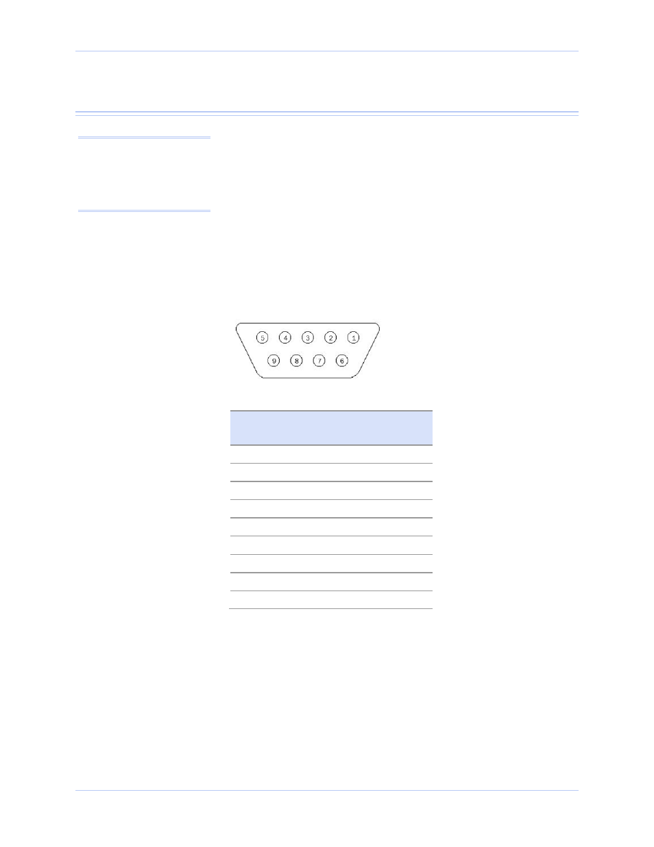
Figure 17 - RS-422/485 DB-9 pin designations
Table 3 - RS-422/485 DB-9 signal definitions
RS-422/485 signal description
DB-9 pin
Auxiliary Output (AuxOut+)
1
Transmit Data (TxD+)
2
Signal Ground
3
Receive Data (RxD+)
4
Auxiliary Input (AuxIn+)
5
Auxiliary Output (AuxOut–)
6
Transmit Data (TxD–)
7
Receive Data (RxD–)
8
Auxiliary Input (AuxIn–)
9
Note: Please refer to Setting
Advanced Options in the
section on Using Device
Manager for details on
software-selectable advanced
options for RS-422/485.