5 connection of the pneumatic switchich facility – VEGA VEGASOURCE 35 User Manual
Page 28
28
5 Connection of the pneumatic switchich facility
VEGASOURCE 35 •
38132-EN-130415
5 Connection of the pneumatic switchich
facility
5.1 Connection of the proximity switches
These instructions apply to source containers VEGASOURCE 35 ver-
sion K, L, M, N with pneumatic switching facility.
Always keep in mind the following safety instructions:
•
Connect only in the complete absence of line voltage
•
If overvoltage surges are expected, overvoltage arresters should
be installed
Connect the proximity switches according to the following diagrams.
Take note of the general installation regulations. As a rule, connect
VEGASOURCE 35 to vessel ground (PA), or in case of plastic ves-
sels, to the next ground potential. On the upper side of the instrument
protective cover there is a ground terminal between the cable entries.
This connection serves to drain off electrostatic charges. In Ex ap-
plications, the installation regulations for hazardous areas must be
given priority.
The data for power supply are specified in chapter "Technical data".
The instrument is connected with standard two-wire cable without
screen.
Use cable with round cross-section. A cable outer diameter of
5 … 10 mm (0.2 … 0.39 in) ensures the seal effect of the cable gland.
If you are using cable with a different diameter or cross-section,
exchange the seal or use a suitable cable gland.
Suitable proximity switch: Pepperl+Fuchs 181094-NCB2-12GM35-
NO-10M
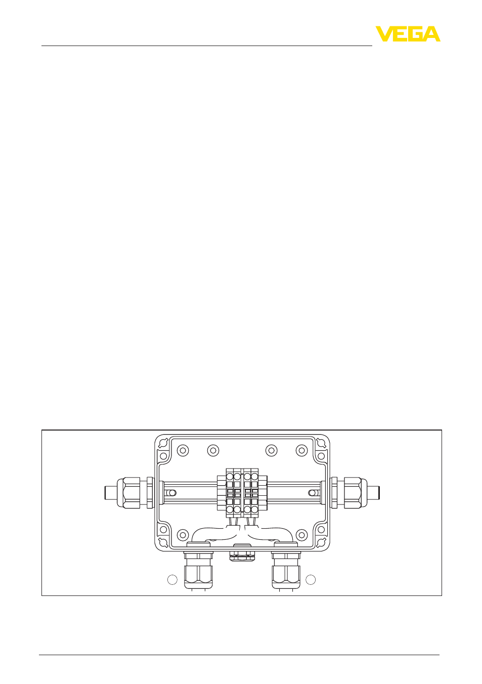
1
2
1 2 3 4
br bl br bl
+ - + -
Fig. 21: Connection of the proximity switches
1 Proximity switch for switch position EIN - ON (terminals 1 and 2)
2 Proximity switch for switch position AUS - OFF (terminals 3 and 4)
Safety instructions
Potential equalisation
Connection cable
Electrical connection