Vegator 532 s1 – VEGA VEGATOR 532 S1 User Manual
Page 2
2
VEGATOR 532 S1
Product description
VEGATOR 532 S1
VEGATOR 532 S1 is a special version. There
are the following differences to VEGATOR
532 Ex:
- no approval for use in hazardous areas
- use of probes with Ex approval only so
that line break monitoring is available
- channel 2 without function
- relay and transistor output of channel 2
output the fault signal. The technical data of
the outputs remain unchanged
- A/B mode for channel 2 is deleted
- potentiometer for channel 2 without function
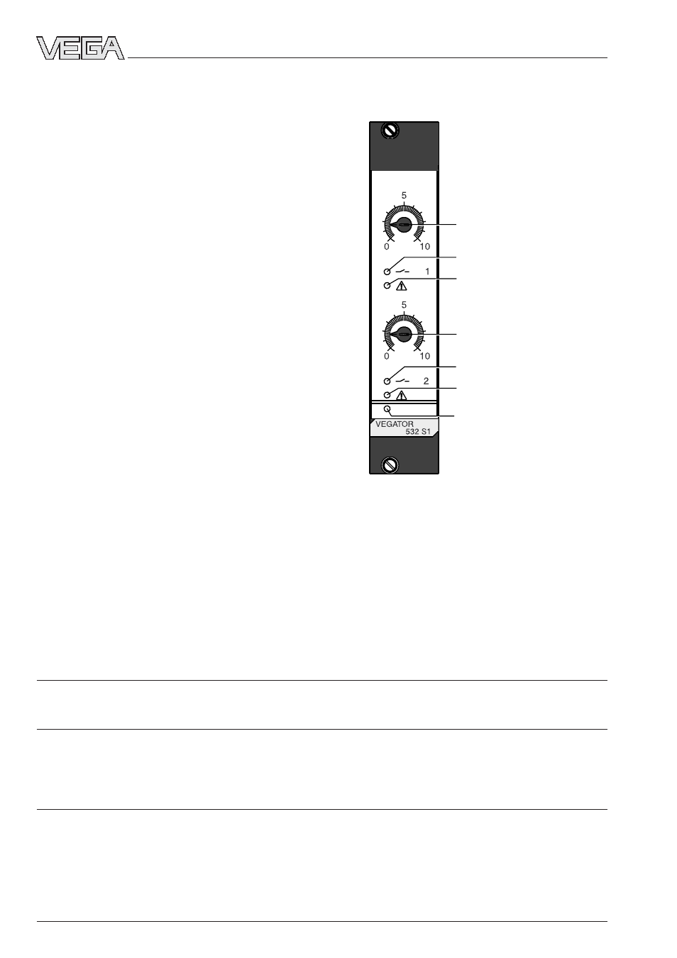
Signal lamps
LEDs in the front plate indicate operation,
switching condition of the relay outputs and
fault message.
- two yellow LEDs for status indication of the
relay and transistor outputs
- LED lights = relay energized, transistor
conducts
- LED extinguished = relay de-energized,
transistor blocks
- two red LEDs for failure indication of
channel 1.
- one green LED for indication operating
voltage „on“.
Meas. data input (only channel 1)
Quantity
1
Relay outputs
Quantity
2
Level relay
1
Fail safe relay
1
Transistor outputs
Quantity
2
Level transistor
1
Fail safe transistor
1
T
T
T
T
Technical data see operating instructions manual Conduktive electr
echnical data see operating instructions manual Conduktive electr
echnical data see operating instructions manual Conduktive electr
echnical data see operating instructions manual Conduktive electr
echnical data see operating instructions manual Conduktive electrodes.
odes.
odes.
odes.
odes.
LED Statusanzeige
Relaisausgang 1
LED Störmeldung
Potentiometer Kanal 1
Schaltpunkteinsteller
Potentiometer ohne Funktion
LED Statusanzeige
Störmelderelais
LED Störmeldung
LED Betriebsspannung
Technical data