Caution, Installation guide, Operation – Veris Industries H971 Install User Manual
Page 2: Troubleshooting, Scaling, Span setting, Led indicator blink codes, Veris industries
VERIS INDUSTRIES
INSTALLATION GUIDE
H971/971SP
Z205412-0D
PAGE 2
©2009 Veris Industries USA 800.354.8556 or +1(0)503.598.4564 / [email protected]
09091
Alta Labs, Enercept, Enspector, Hawkeye, Trustat, Veris, and the Veris ‘V’ logo are trademarks or registered trademarks of Veris Industries, L.L.C. in the USA and/or other countries.
opEration
The H971 is a current-sensitive device that monitors DC current (amperage) in the
conductor passing through it. The unit uses Pulse Reset Technology™ with proven
transducer circuitry to produce a status output suitable for connection to building
controllers or other appropriate data acquisition equipment. The H971 requires 12-
24VDC to generate its output. The H971 has a user-adjustable span to allow flexibility.
The H971SP comes factory calibrated at a fixed span for maximum accuracy.
The H971 is ideal for DC current monitoring where accuracy must be maintained in
the presence of magnetic fields, current spikes, and high fault currents (e.g. solar
panels, electroplating equipment).
The H971 housing offers unprecedented mounting flexibility. The mounting bracket
can be attached in three different places. Additionally, the bracket is compatible with
the Veris AH01 DIN Rail clip, allowing DIN mounting.
troublEshooting
Problem
Solution
The LED is off and no signal is
produced
Verify that at least 12V supply voltage is applied to PWR
(+) and GND (-) terminals.
The LED is on solid and the
output is at maximum
Verify that the unit is not attempting to monitor more
than ±200A.
scaling
SENSED AMPS
4mA
12mA
-200A*
+200A*
0A
20mA
SENSOR OUTPUT
*Field Adjustable from ±20A to ±200A
(not applicable to customer-specified factory scaled models)
span sEtting
(not applicable to the H971SP models)
The H971 comes preset at the maximum (0-200A) span. To adjust the H971 to a
different span, locate the potentiometer on the top of the device. This potentiometer
is a multi-turn device, taking about 23 turns to adjust the span from ±20A to ±200A.
Use the potentiometer to adjust the maximum amperage range used by the sensor.
The smallest amperage range (0 to ±20 A) is set by turning the potentiometer fully
counterclockwise; the greatest amperage range (0 to ±200 A) is set by turning the
potentiometer fully clockwise.
S
E
I
R
T
S
U
D
N
I
S
I
R
E
V
3
2
2
7
9
n
o
g
e
r
O
,
d
n
a
lt
r
o
P
6
5
5
8
-
4
5
3
-
0
0
8
-
1
1
7
9
!
Span
Current
Flow
4-20
mA
12-24
VDC
Gnd P
ower
200A DC Current Sensor
Fully CCW:
smallest range
(0 to 20A)
Fully CW:
greatest range
(0 to 200A)
To determine the best amperage range for an application, first set the load to
the maximum amperage that will be used. Use the LED as a guide to adjust the
potentiometer to its optimum setting. Verify the measured output current matches
the load current using a current clamp meter.
LED Activity
Potentiometer Adjustment
Steady green blink
Turn CCW until LED blinks rapidly, then slowly turn CW just until
blink returns to steady rate.
Rapid green blink
Turn CW until LED blinks at a steady rate.
An alternate adjustment method that does not require a current clamp meter can
also be used, provided the amperage flowing in the conductor is steady for the
duration of the adjustment. In this example, it is assumed that the H971 is initially
set to the maximum 0-200A span, but the installer has decided to reduce the span to
0-120A. Sample numbers are provided to illustrate the calculations.
Action
Example
Determine the device output using a portable multimeter or the
automation controller.
15
The H971 is bi-directional, so a 12mA output corresponds to a 0A
load in the conductor. Determine the output above the 0 level by
subtracting 12mA.
15 - 12 = 3
Multiply by the initial maximum span setting before adjustment.
3 x 200 = 600
Divide by the desired maximum span.
600 / 120 = 5
Add 12 to this value to get the new output value.
5 + 12 = 17
Turn the potentiometer counterclockwise until the output reads 17mA.
This is the output for the amperage load at a span of 0-120A.
17
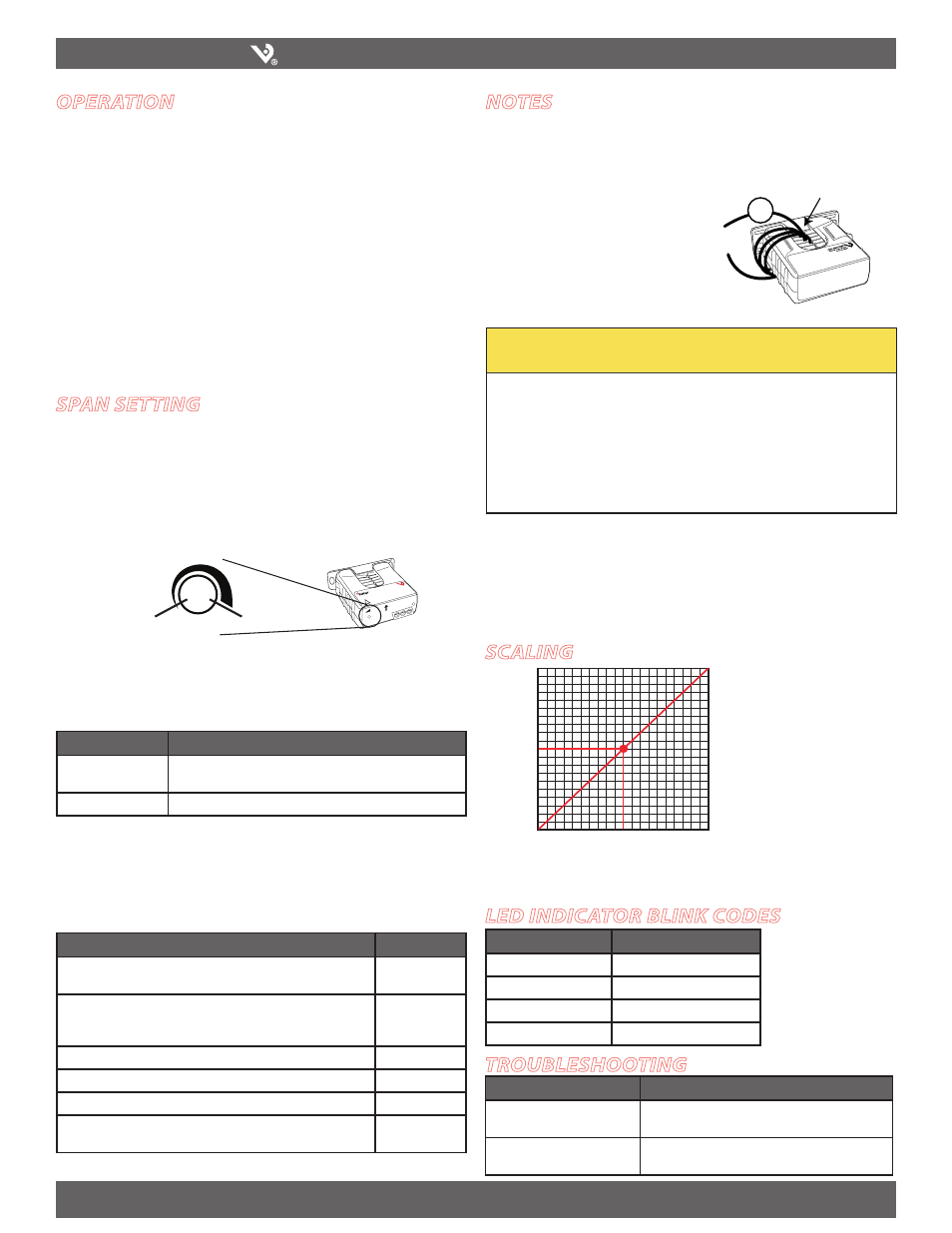
notEs
For load currents less than 2A:
Wrap the monitored conductor through the center hole and around the sensor body
to produce multiple turns through the "window." This increases the current measured
by the transducer.
Controller must be programmed to account for
the extra turns. e.g., if four turns pass through
the sensor (as shown) the normal controller
reading must be divided by 4.
Accuracy may be reduced if wraps are used.
4x
1A
CAUTION
RISK OF EQUIPMENT DAMAGE
• Derate the product’s maximum current for the number of turns
through the sensing window using the following formula.
Rated Max. Amps ÷ Number of Turns = Max. monitored Amps
e.g. : 100A ÷ 4 Turns = 25 Amps max. in monitored conductor
• Failure to follow these instructions can result in overheating
and permanent equipment damage.
Failure to observe the following can result in incorrect output readings:
Observe the arrow on the H971 showing positive current direction so that the
1.
output will have proper polarity for the application.
Do not expose the H971 to continuous current levels greater than 200A RMS (brief
2.
current surges and fault currents should not adversely affect the H971).
lED inDicator blink coDEs
LED Activity
Status Description
Single green
Normal operation
Double green
Over span
Red/green
Over limit
Solid red
Overload