Installation guide, Operation, Installation – Veris Industries H804x SERIES Install User Manual
Page 2: Product diagram, H804x series, Disconnect and lock out power before installation
H804x SERIES
Z201700-0F
PAGE 2
©2008 Veris Industries USA 800.354.8556 or +1.503.598.4564 / [email protected]
10101
Alta Labs, Enercept, Enspector, Hawkeye, Trustat, Veris, and the Veris ‘V’ logo are trademarks or registered trademarks of Veris Industries, L.L.C. in the USA and/or other countries.
TM
INSTALLATION GUIDE
OPERATION
The H8040 Series devices combine microprocessor-based kW transducers and
high-accuracy split-core instrument grade current transformers (CTs) in a single
unit. Integration of electronics lowers hardware and installation costs. The sensors
automatically detect phase reversal, so CT load orientation is not a concern. The
CTs and meters are calibrated as a set, so it is necessary to color-match the CTs and
voltage leads when installing.
The H8041 and H8042 are for single-phase or balanced-load applications at 208V and
480V, respectively. The H8043 and H8044 are the three-CT versions of the product for
use on 208V and 480V with unbalanced loads.
These devices are used in chiller optimization, performance contracting, and energy
management. The 1% total system accuracy conforms to ANSIC12.1 metering
standards.
INSTALLATION
Disconnect and lock out power before installation.
The Enercept meter, including the current transformers (CTs), voltage connection
fuses, and fusepac, is permitted within electrical distribution equipment including
but not limited to panelboards, switchboards, motor control centers, and
transformers. Carefully review the equipment in which the Enercept meter will be
installed. The following installation conditions should be considered during the
installation process:
• Review the equipment enclosure for ventilation openings. Wires will cross
many of these openings in a normal installation, however, do not install
the Enercept where it will substantially block ventilation openings in the
enclosure.
• The Enercept meter and the wiring installed within a wiring space
or gutter should not exceed 75 percent cross sectional fill at the
Enercept meter parts as addressed in the NEC. Improper installation of
Enercept meter in the wire gutter of equipment may affect the thermal
performance of the equipment.
• The arrangement of CTs within the equipment must also be considered to
ensure the bending radius of conductors is not adversely affected.
• Review the arrangement and location of the CTs within the equipment.
The CT must not create undue strain on the conductor. A CT may require
appropriate support in order to address such a condition.
1. Connect the voltage leads to the 3 phase conductors, at a location that is not
normally turned off. Connect voltage leads on the Line side of the conductor to
ensure constant power to the meter. Connect the red lead first to the conductor
most conveniently located to the output connector. See the Wiring section on the
following page.
2. Snap the CT onto the conductor.
Observe color matching. If the
application can exceed 20 times the
rated CT current, use wire ties to
secure the I-bar to the CT housing.
This CT automatically detects phase
reversal, so CT load orientation is
not important.
3. Attach the 4-20mA output wires as shown. Observe (+), (-), and Shield polarity.
Insulate any exposed wiring.
SHIELD
S
(+)
(+)
External
Power (24 VDC)
PS-24
PANEL
(-)
Common
4-20mA Input
(-)
(s)
4. Check power reading (these calculations are approximations only).
Expected power:
4-20mA response:
kW = Volts x Amps x 1.732 x PF / 1000
kW demand = kW x (mA out - 4) / 16
kW = Horsepower x 0.746
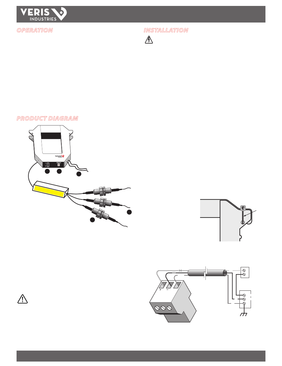
PRODUCT DIAGRAM
Fuse P
ack
Enercept
®
1
2
2
3
4
2
5
2
1. Voltage Leads: input range is 208 to 480V, 50/60Hz.
2. Fuses: maximum current draw 60mA. Fuses provided by the factory are rated
1/2A, 600VAC, 200 KAIC. Replace only with fuses of the same type and rating.
3. 4-20mA Output connector
4. Status LED: blink codes: slow green for normal operation; slow red for incorrect
wiring or low power factor (less than 0.5); fast red for max. current exceedance.
5. External CTs (3-phase version only): permanently attached; do not disconnect or
use with other power meters.
Color match CTs and voltage leads! Example: clamp the red
labeled CT around the power conductor connected to the
red voltage wire.
Wire tie