Calibration (h321 only) troubleshooting, Calculate the maximum and target readings, Set span – Veris Industries H321 Install User Manual
Page 4
Z201199-0G
Page 4 of 4
©2013 Veris Industries USA 800.354.8556 or +1.503.598.4564 / [email protected] 06131
Alta Labs, Enercept, Enspector, Hawkeye, Trustat, Aerospond, Veris, and the Veris ‘V’ logo are trademarks or registered trademarks of Veris Industries, L.L.C. in the USA and/or other countries.
Other companies’ trademarks are hereby acknowledged to belong to their respective owners.
Installation Guide
Current Sensors
H321/H321SP
TM
2. Calculate the maximum and target readings.
A. Determine the maximum current likely to occur in the application.
The following calculation is given as an example and uses
sample current values. In an actual application, any values
appropriate to the application (within the range of the device)
can be substituted.
The H321SP is factory-calibrated.
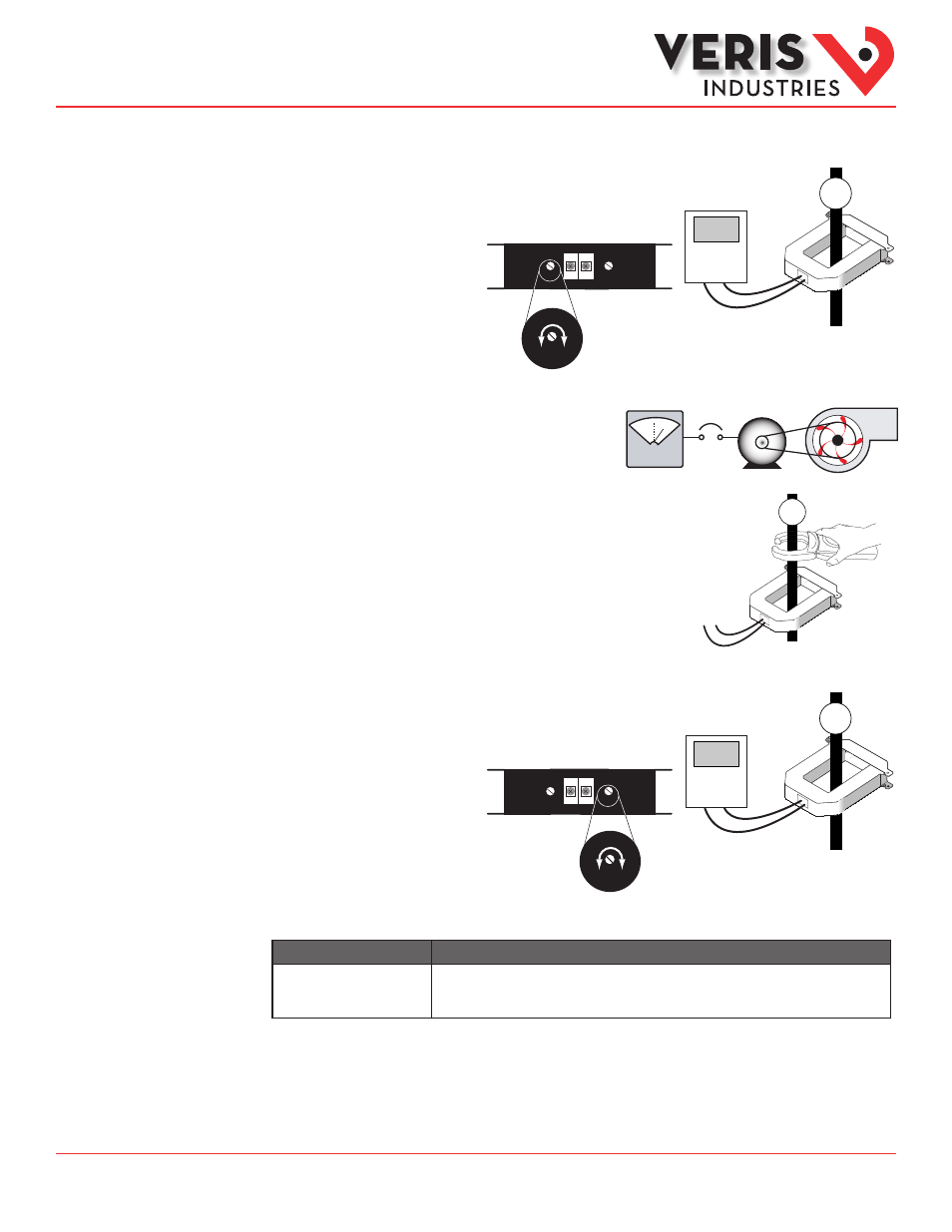
1. Set Zero.
Apply power to the sensor with no load in
the monitored conductor. Turn the zero
setpoint screw until the controller reads
4 mA output.
B. Establish normal load conditions on the conductor. Measure this current using
an external measurement device, such as a portable amp clamp.
C. Calculate target output:
If A = the max. current, and B = the reading from the amp clamp, then:
target output =
e.g. target output = = 16 mA
3. Set Span.
Turn the span setpoint screw until the controller reading equals the target output.
Calibration
(H321 Only)
Troubleshooting
Problem
Solution
No Reading at Controller
• Confirm that a 12-30 VDC power supply is in series with the sensor output terminals and the control
panel analog input terminals.
• Assure that sensor core mating surfaces are clean and that the core clamp is completely closed.
0A
Controller:
4mA Output =
0A Load
0A
Zero
Zero
Out
Span
300 800
A
OK!
600 A
450 A
800
300
Zero
Out
Span
300 800
16 mA x — + 4 mA
B
A
16 mA x — + 4 mA
450
600
450 A
Controller:
16 mA Output
= 450 A Load
450 A