Wiring diagram, Switch indication, Fv-08vkml2 – Panasonic FV-08VKML2 User Manual
Page 5: Fv-08vksl2
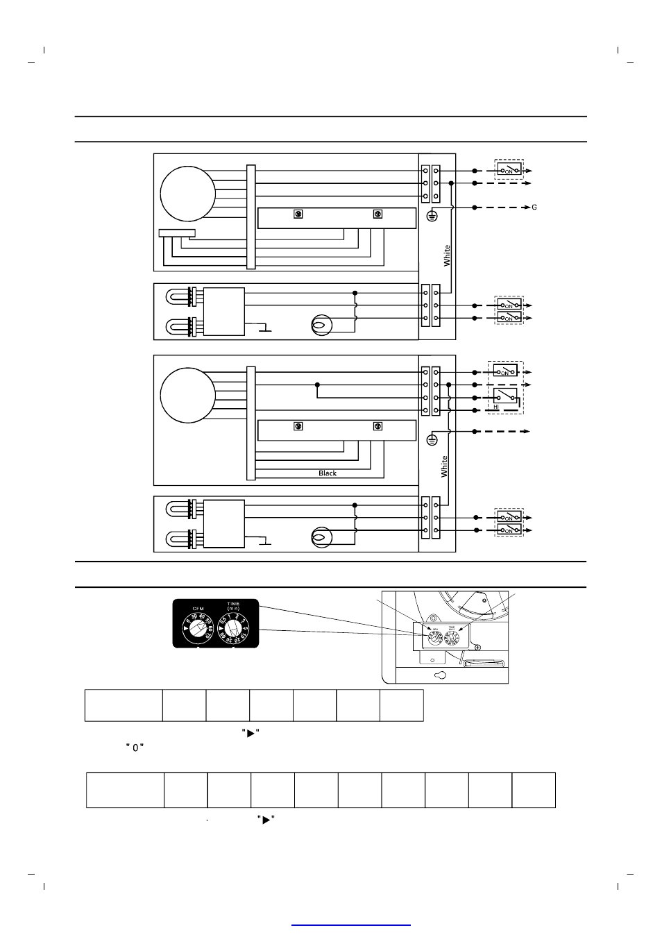
FV-08VKML2
WIRING DIAGRAM
Fan body
Junction box
Switch box
L
N AC120V 60Hz
Black
White
Green
Black
Red
Adjustment switch
Main control circuit
Black
White
Red
Blue
Orange
Purple
DC-Motor
Sensor
Red
White
Yellow
Black
Red
White
Yellow
Black
White
Black
Black
Black
Black
Switch box
L
L
Night lamp
Green
Electronic
Ballast
Lamp
Lighting unit
FV-08VKSL2
Fan body
Junction box
Switch box
L
N
White
Red
Black
Red
Green
G
Black
White
Red
Red
Adjustment switch
Black
White
Red
Blue
Orange
Purple
DC-Motor
Main control circuit
Red
White
Yellow
Lighting unit
Black
Black
White
Green
Night lamp
L
L
Switch box
Black
Black
Lamp
Electronic
ballast
SWITCH INDICATION
Low speed air volume
preset switch
High/low delay time
preset switch
Switch indications
on blower unit
Low speed air-volume preset switch positions
Air Volume
[CFM]
0
30
40
50
60
70
Factory setting: 50 CFM. Position
: Use for factory test only.
Position
Fan stop
:
High/Low delay time preset switch positions
Delay Time
[min]
0.5
1
2
3
5
10
20
30
60
Factory setting: 20 minutes. Position
: Use for factory test only.
Air volume preset switch
Delay time preset switch
White
Air volume preset switch
Delay time preset switch
5
Power supply
AC120V 60Hz
AC120V 60Hz
Power supply
AC120V 60Hz
Power supply
Power supply
PDF created with pdfFactory Pro trial versi