Êten s io n settin gs, Ëbelt tension measurements – Milnor K36 0005R User Manual
Page 4
MS
SM0
2
0
4
AE
/8
33
2BV
(1
of
1)
È
V-BELT TENSION ADJUSTMENTS FOR
30" AND
36" B-TYPE
M
ACHINES AND
42" Q-
TYPE MACHINES
This
ins
truct
ion i
s t
o
be us
ed for
adjus
ti
ng t
h
e bel
t
tens
ion
on t
h
e fol
lowi
n
g
m
achine m
odes:
30016B
WE
42026QHE
36021B
WE
42026QTG
360326QWE
42026QTH
42026QWE
A belt
tens
ion t
est
ing devi
ce (Mi
lnor
®
part
num
ber 30T001)
and
a
st
raight
edge are required when us
ing t
h
ese i
n
st
ructi
ons.
Ê
Ten
s
io
n Settin
gs
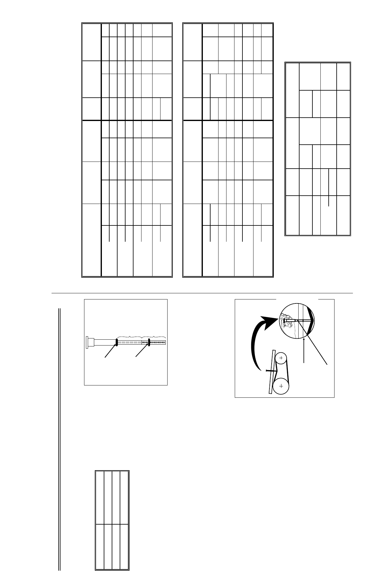
Set
the o-ri
ngs on t
h
e tens
ion t
est
ing devi
ce (see F
IGURE 1) as
foll
ows:
1.
M
ove the upper o-ri
ng to t
h
e topm
ost
posi
ti
on, rest
ing agai
nst
the bot
tom
edge of the cap.
2.
F
ind t
h
e proper belt
deflect
ion s
ett
ing (by m
achine m
odel and bel
t funct
ion) i
n
the appropri
ate t
able bel
o
w.
3.
M
ove the l
o
wer o-ring on t
h
e tens
ion t
est
er to t
h
is
deflect
ion s
ett
ing on t
h
e inches
scal
e.
NOT
E
1:
The t
ensi
on tes
ti
ng device i
s m
arked on the one s
ide i
n
inches
and pounds and on t
h
e other s
ide i
n
cen-
ti
met
ers and ki
logram
s. Al
l val
u
es i
n
the t
ables
are marked.
NOT
E
2:
The i
n
st
ructi
on sheet
provided wi
th t
h
e tens
ion t
est
ing devi
ce shoul
d not be us
ed. Use onl
y the i
n
st
ruc-
ti
ons provi
ded herein.
NOT
E
3:
The reference (ref.) codes
shown i
n
the t
ables
are for factory us
e
only.
Ë
Belt Tension Measurements
1.
Place a s
trai
ght edge al
ong the t
op edge of the bel
t t
o
be tes
ted s
o
that
it
spans bot
h pull
eys. P
lace t
h
e tension t
est
er in t
h
e center of t
h
e belt
and press
and down on the cap unt
il
the l
o
wer o-ring i
s i
n
li
ne wit
h
the s
trai
ght edge, as
shown.
2.
R
ead the s
ett
ing of t
h
e upper o-ring on t
h
e LBS
scal
e of the t
ensi
o
n
te
st
er
.
3.
Com
p
are thi
s val
u
e wit
h
the accept
able range i
n
the appropri
ate t
able.
If the bel
t i
s brand new (has
never been run), use t
h
e range in t
h
e In-
it
ia
l Tension col
u
mn. If t
h
e belt
is not brand new, l
o
cate t
h
e accept
-
able range i
n
the F
inal
Tensi
on colum
n
.
4.
If t
h
e reading on t
h
e tens
ion t
est
er is
les
s t
h
an the range s
hown in t
h
e tabl
e, the bel
t i
s t
oo loos
e and mus
t be
ti
ghtened. If t
h
e reading i
s great
er than t
h
e range shown i
n
the t
able, t
h
e belt
is
too t
ight
and mus
t be l
oos-
ened. Adj
u
st
the bel
t unt
il
the readi
ng fall
s wi
thi
n
the accept
able range i
n
the t
able.
Ï
30016BWE 36021BWE
Be
lt
Def
lect.
(i
nches)
Init
ia
l
Tensio
n
(l
bs
.)
(ref
.)
Init
ia
l
Tensio
n
(l
bs
.)
(ref
.)
Be
lt
Deflect
(I
N)
Init
ia
l
Te
n
si
o
n
(lbs
.)
(ref
.)
Init
ia
l
Te
n
si
o
n
(l
b
s.)
(r
ef
.)
WA
S
H
/ 2
SPE
E
D
WASH
5
0
C
5
/1
6
6
.6
– 9.
2
K
P3
5.
1 – 7.
1
K
N
1
3/
3
2
2.
4 – 2.
8
D
P2
2 – 2.
4
D
N
6
0
C
1
1/
3
2
2
.4
–
2
.8
4
D
P
2
2
.0
– 2.
4
D
N
1
3/
3
2
2.
4 – 2.
8
D
P2
2 – 2.
4
D
N
D
R
A
IN
5
0
C
5
/16
9.
6 – 13
.0
MP
3
7
.4
– 10
.0
MN
25
/6
4
9
.6
– 13
.0
MP
3
7
.4
–
1
0
.0
MN
6
0
C
1
1/
3
2
2.
8 – 4.
0
E
P2
2
.4
–
3
.3
7
E
N
1
3
/3
2
2
.8
– 4.
0
E
P2
2.
4 – 3.
4
E
N
HIGH
SPE
E
D
EXT
R
AC
T
50
C
2
5
/64
10
.5
–
1
4
.3
N
P
3
8
.1
–
11
.0
N
N
27
/6
4
1
0
.5
–
1
4
.3
N
P
3
8
.1
–
11
.0
N
N
60
C
2
5
/64
8.
0 – 11
.0
L
P
3
6
.2
–
8
.5
L
N
2
7
/64
9.
6 – 13
.0
MP
3
7
.4
– 10
.0
MN
LOW
SPE
E
D
EXT
R
AC
T
50
C
1
1
/64
9.
0 – 13
.0
MP
3
7
.4
– 10
.0
MN
11
/6
4
6.
6 – 9.
2
K
P3
5.
1 – 7.
1
K
N
60
C
5
/3
2
1
1
/64
Ï
36026QWE 42026QWE
Be
lt
Def
lect.
(i
nches)
Init
ia
l
Te
n
si
o
n
(l
bs
.)
(
ref.
)
Init
ia
l
T
ension (
lbs.)
(ref
.)
Be
lt
Deflect
(I
N)
Init
ia
l
Tensio
n
(l
bs
.)
(ref
.)
Init
ia
l
Te
n
si
o
n
(l
b
s.)
(r
ef
.)
WA
S
H
/ 2
SPE
E
D
WASH
50
C
1
3
/32
2.
4 – 2.
84
D
P
2
2
.0
–
2
.4
D
N
11
/3
2
9
.6
– 13
.0
MP3
7.
4 – 10
.0
MN
60
C
1
3
/32
23
/6
4
2.
8 – 4.
0
D
R
A
IN
5
0
C
25
/6
4
9
.6
– 13
.0
MP
3
7
.4
– 10
.0
MN
23
/6
4
EP2
2
.4
– 3.
4
E
N
6
0
C
1
3/
3
2
2.
8 – 4.
0
E
P2
2
.4
–
3
.3
4
E
N
2
3
/6
4
1
0.
5 – 14
.3
HIGH
SPE
E
D
EXT
R
AC
T
50
C
7
/1
6
9
.6
– 13
.0
MP
3
7
.4
– 10
.0
MN
7
/16
9.
6 – 13
.0
N
P
3
8
.1
– 11
.0
N
N
60
C
7
/1
6
8
.0
– 11
.0
L
P
3
6
.2
–
8
.5
L
N
7
/1
6
9
.6
– 13
.0
MP
3
7
.4
– 10
.0
MN
LOW
SPE
E
D
EXT
R
AC
T
50
C
3
/1
6
9.
6 – 13
.0
MP
3
7
.4
– 10
.0
MN
1/
4
6.
6 – 9.
2
MP
3
7
.4
– 10
.0
MN
6
0
C
3
/1
6
1
/4
KP3
5
.1
–
7
.1
K
N
Ï
42
02
6Q
HE, Q
T
G, Q
T
H
Be
lt
D
ef
l.
(i
nches)
Init
ia
l Tensio
n
(l
b
s.)
(
re
f.
)
F
ina
l T
ension
(l
b
s.)
(r
ef
.)
WA
S
H
/
2
SPE
E
D
WASH
19
/6
4
9
.6
2 – 13
.0
M
P
3
7
.4
– 10
.0
M
N
D
R
A
IN
5
/3
2
1
0.
5 – 14
.3
8.
1 – 11
.0
M
A
IN
5
0
C
3
1
/64
1
0
.5
– 14
.3
N
P
3
8
.1
– 11
.0
N
N
60
C
1
5/
3
2
OPTI
ONAL LOW
S
P
E
ED
EX
R
A
CT
1
9
/6
4
8
.0
– 11
.0
LP
3
6
.2
– 8.
5
L
N
Upper
o-
ri
ng
Deflec
tion
F
o
rc
e Sc
ale
(R
ead Down)
Deflec
tion Dis
-
tance Sc
ale
(R
ead Up)
Lower
o-
ri
ng
Î
FIG
URE 1
(M
SSM0
2
0
4
AE)
Î
Tensi
on Tester
Scal
es
Lower
o-
ri
ng
Str
a
ight
Edge
Î
FI
GURE 2
(M
SSM
0
2
0
4
AE)
Î
Taking Measur
em
ents
w
ith the
Tensi
on Tester
2