Step 6: check pilot and burner operation, Nstallation – Southbend HEAVY DUTY COUNTERLINE HDG-48 User Manual
Page 11
H
EAVY
D
UTY
C
OUNTERLINE
I
NSTALLATION
O
WNER
’
S
M
ANUAL
1192662 P
AGE
11
INSTALLATION
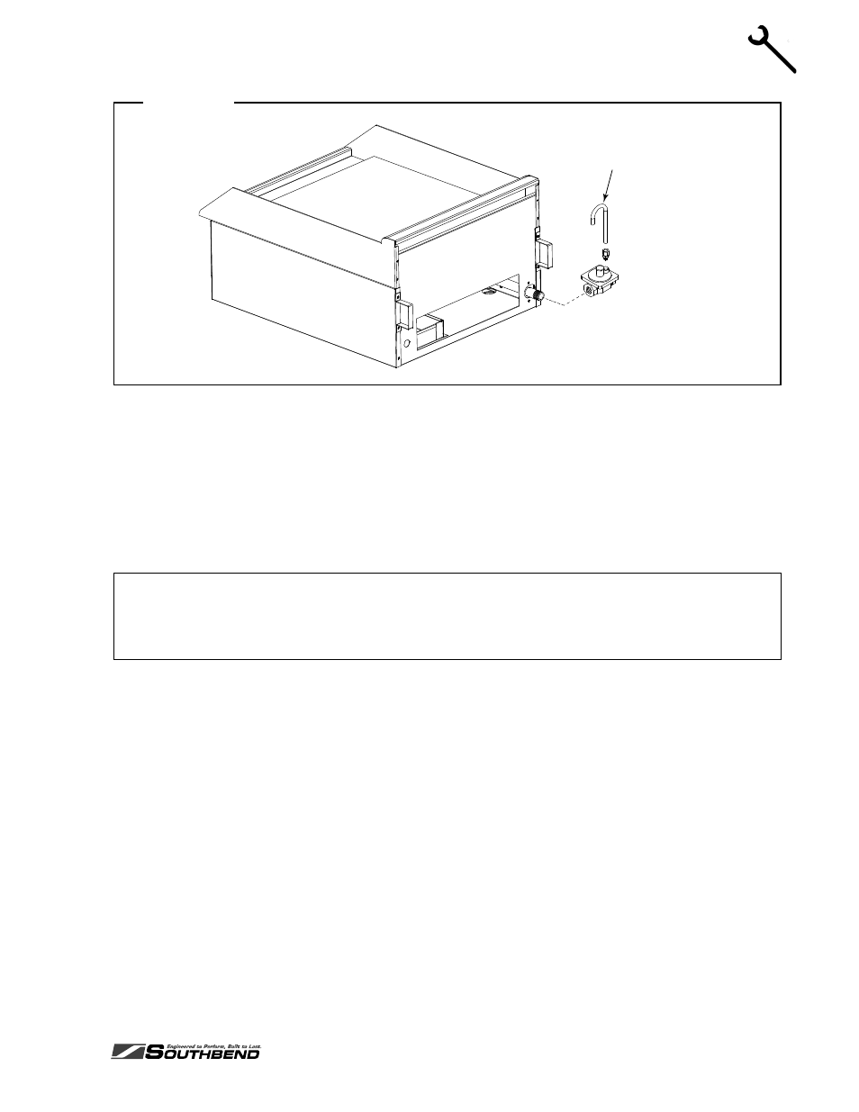
Figure 4
Vent tube included on griddles
built after June 19, 2006.
Step 5: Final Positioning, Clearance Check, and Ventilation Check
1. Position the appliance where it will be operated.
2. Check that the appliance surface is level. The length of each leg is adjustable by screwing the bottom
portion of the leg in or out. The appliance must be level for proper operation!
3. Check for adequate clearances around the appliance (see page 5).
4. Check for adequate ventilation (see page 5).
NOTICE
In the Commonwealth of Massachusetts all gas appliances vented by either mechanical systems or
ventilation hoods shall comply with 248 CMR interlocking requirements.
Step 6: Check Pilot and Burner Operation
All appliances are adjusted at the factory. However, pilot heights, burner air shutters, and thermostatic
valves should be checked at installation and adjusted if necessary. Do the following:
1. Turn main gas supply “ON”.
2. Check the manifold gas pressure using the procedure on page 20.
3. Light the pilots as described in the Operation section of this manual.
4. Check (and, if necessary, adjust) the pilot flame heights using the procedure on page 21.
5. Light the burners. Set the control knobs to only low temperatures for now.
6. Check (and, if necessary, adjust) the burner air shutters using the procedure on page 21.
Step 7: Final Installation Steps for Griddle Models
This step applies only to the installation of griddle models. New griddles should be carefully tempered and
cared for in order to avoid possible damage. To break in a new griddle, do the following:
1. Wipe the griddle surface clean.
- HEAVY DUTY COUNTERLINE HDG-48-RE HEAVY DUTY COUNTERLINE HDG-60 HEAVY DUTY COUNTERLINE HDG-72-RE HEAVY DUTY COUNTERLINE HDG-36 HEAVY DUTY COUNTERLINE HDG-60-RE HEAVY DUTY COUNTERLINE HDG-48-M HEAVY DUTY COUNTERLINE HDG-72 HEAVY DUTY COUNTERLINE HDG-24-M HEAVY DUTY COUNTERLINE HDG-36-RE HEAVY DUTY COUNTERLINE HDC-24 HEAVY DUTY COUNTERLINE HDG-60-M HEAVY DUTY COUNTERLINE HDG-24 HEAVY DUTY COUNTERLINE HDG-36-M HEAVY DUTY COUNTERLINE HDG-72-M