1 connector pin assignments, 2 signal descriptions, 3 level requirements – Superior SLO-SYN SS2000MD4 User Manual
Page 16: Ignal, Pecifications
Danaher Motion Superior Electric
SS2000MD4
16
400030-043 Rev G
4.7 S
IGNAL
S
PECIFICATIONS
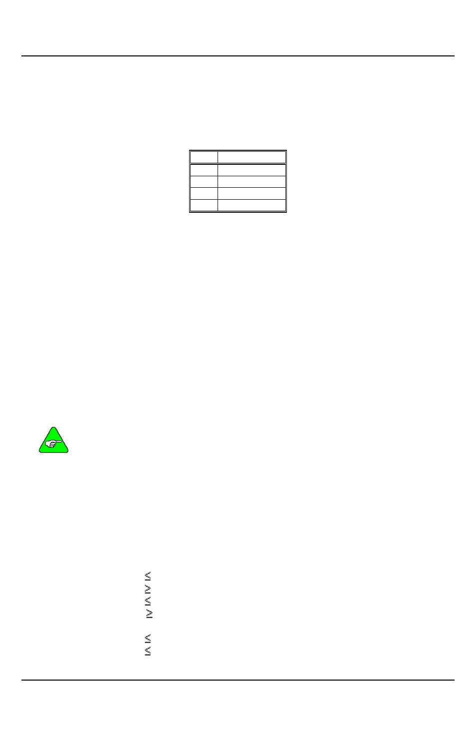
4.7.1 Connector Pin Assignments
All connections are made via the 4-pin terminal strip (J2).
Pin Assignment
1
OPTO
2
PULSE
3
DIR
4
AWO
4.7.2 Signal Descriptions
OPTO
Opto-Isolator Supply
User supplied power for the opto-isolators.
PULSE Pulse Input
A low to high transition on this pin advances the motor one step. The step size is
determined by the Step Resolution switch setting.
DIR
Direction Input
When this signal is high, motor rotation is clockwise. Motor rotation is counter-clockwise
when this signal is low.
Clockwise and counter-clockwise directions are properly oriented when viewing the
motor from the end opposite the mounting flange.
AWO
All Windings Off Input
When this signal is low, AC and DC current to the motor will be zero. There is no
holding torque when the AWO signal is low.
If you are using the drive with an MX2000, SS2000I or SS2000I-V
control, the READY input and the OPTO input on the control must be
jumpered together.
4.7.3 Level Requirements
OPTO
Voltage .................... 4.5 to 6.0 VDC
Current..................... 16 mA per signal used
Other Signals
Voltage
Low................... 0.8 VDC
0.0 VDC
High .................. OPTO
OPTO - 1 volt
Current
Low................... 16 mA
High .................. 0.2 mA