8 voltage regulator adjustment, 1 break-in procedure, 2 using the auto/off/manual switch (figure 3.1) – Generac 004692-2 User Manual
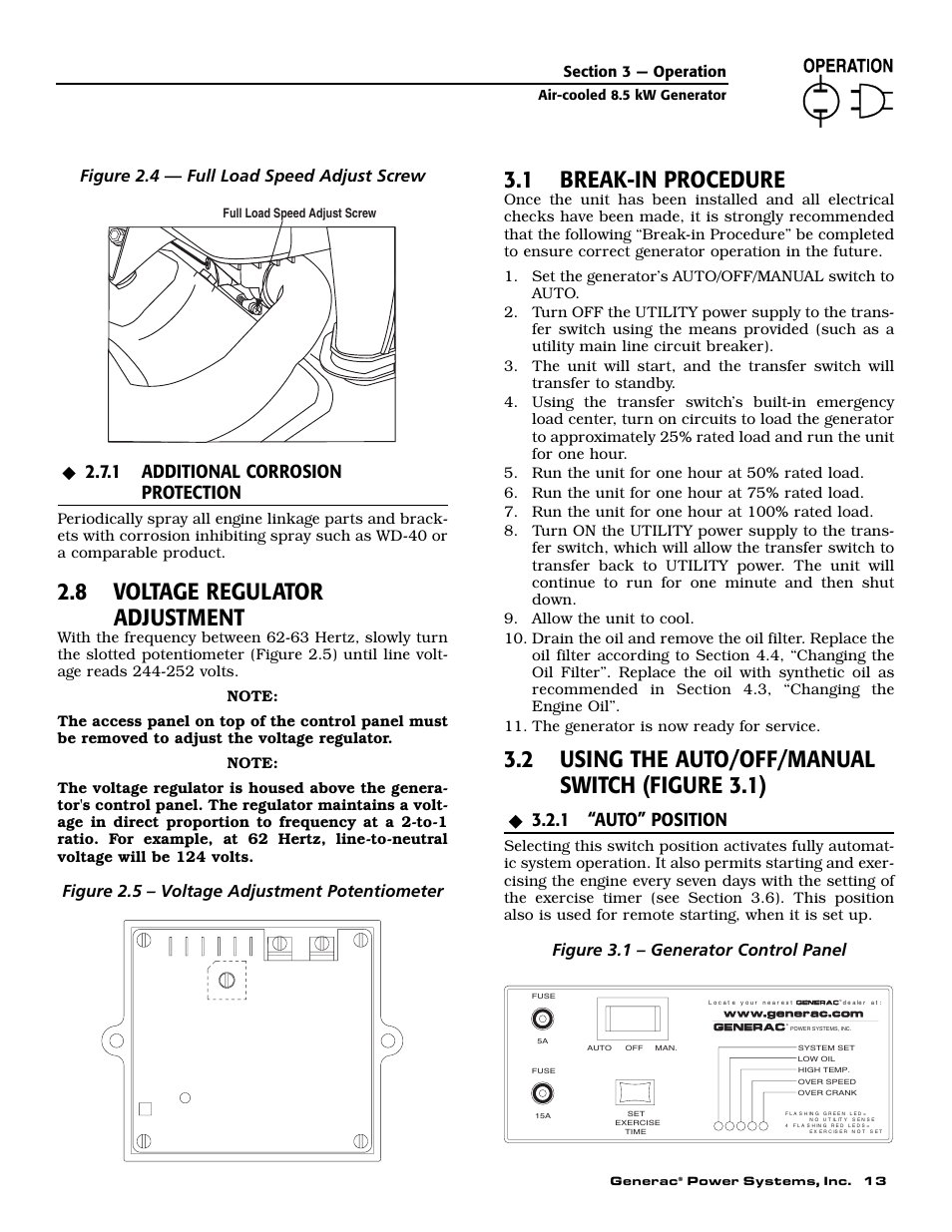
Page 15: 1 additional corrosion protection, 1 “auto” position, Figure 2.4 — full load speed adjust screw, Figure 2.5 – voltage adjustment potentiometer, Figure 3.1 – generator control panel
 8 voltage regulator adjustment, 1 break-in procedure, 2 using the auto/off/manual switch (figure 3.1) | 1 additional corrosion protection, 1 “auto” position, Figure 2.4 — full load speed adjust screw, Figure 2.5 – voltage adjustment potentiometer, Figure 3.1 – generator control panel | Generac 004692-2 User Manual | Page 15 / 52
 See also other documents in the category Generac Generators:
- NP-50LPG (32 pages)
- 004692-0 (44 pages)
- 004707-0 (56 pages)
- 005030-0 (15kW) (60 pages)
- 004475-0 (52 pages)
- 004189-1 (60 pages)
- Generator (16 pages)
- 00941-4 (52 pages)
- 1019-3 (24 pages)
- PRIMEPACT 50 05754-0 (60 pages)
- 04077-1 (32 pages)
- 7500 (20 pages)
- 11400 (16 pages)
- 09290-4 (52 pages)
- DUARDIAN 04079-2 (44 pages)
- 005031-0 (60 pages)
- Guardian Series Standby Gas Engine Generators 005884-1 (4 pages)
- Liquid-Cooled Engine Generator Sets 50Hz (5 pages)
- 004917-5 (48 pages)
- 04390-0 (60 pages)
- 5500EXL (20 pages)
- QT080 (6 pages)
- 005308-0 (48 pages)
- ASPAS1CCL015 (48 pages)
- Guardian Series Standby Generators QT060 (6 pages)
- Guardian Series Residential Standby Generators Air Cooled Gase Engine 005884-1 (5 pages)
- 04675-3 (56 pages)
- 0046265 (64 pages)
- 190/220 (24 pages)
- 005262-0 (56 pages)
- STANDBY GENERATORS 005520-1 (4 pages)
- SVP5000 97193 (16 pages)
- GP 3250 Portable Generator 005982-0 (20 pages)
- 00941-3 (52 pages)
- 004913-2 (52 pages)
- 20kW (52 pages)
- 004626-2 (64 pages)
- 04164-1 (64 pages)
- 004582 (39 pages)
- 005031-2 (56 pages)
- QT030 (4 pages)
- Standby Generator QT022 (6 pages)
- Gn - 410 (24 pages)
- XG8000E 5847-0 (2 pages)