Operation and checkout, Operation, Checkout – Greenheck Fan Modutrol IV Motors 81 User Manual
Page 10: Damper application
SERIES 41 AND 81 MODUTROL IV™ MOTORS
63-2187—3
10
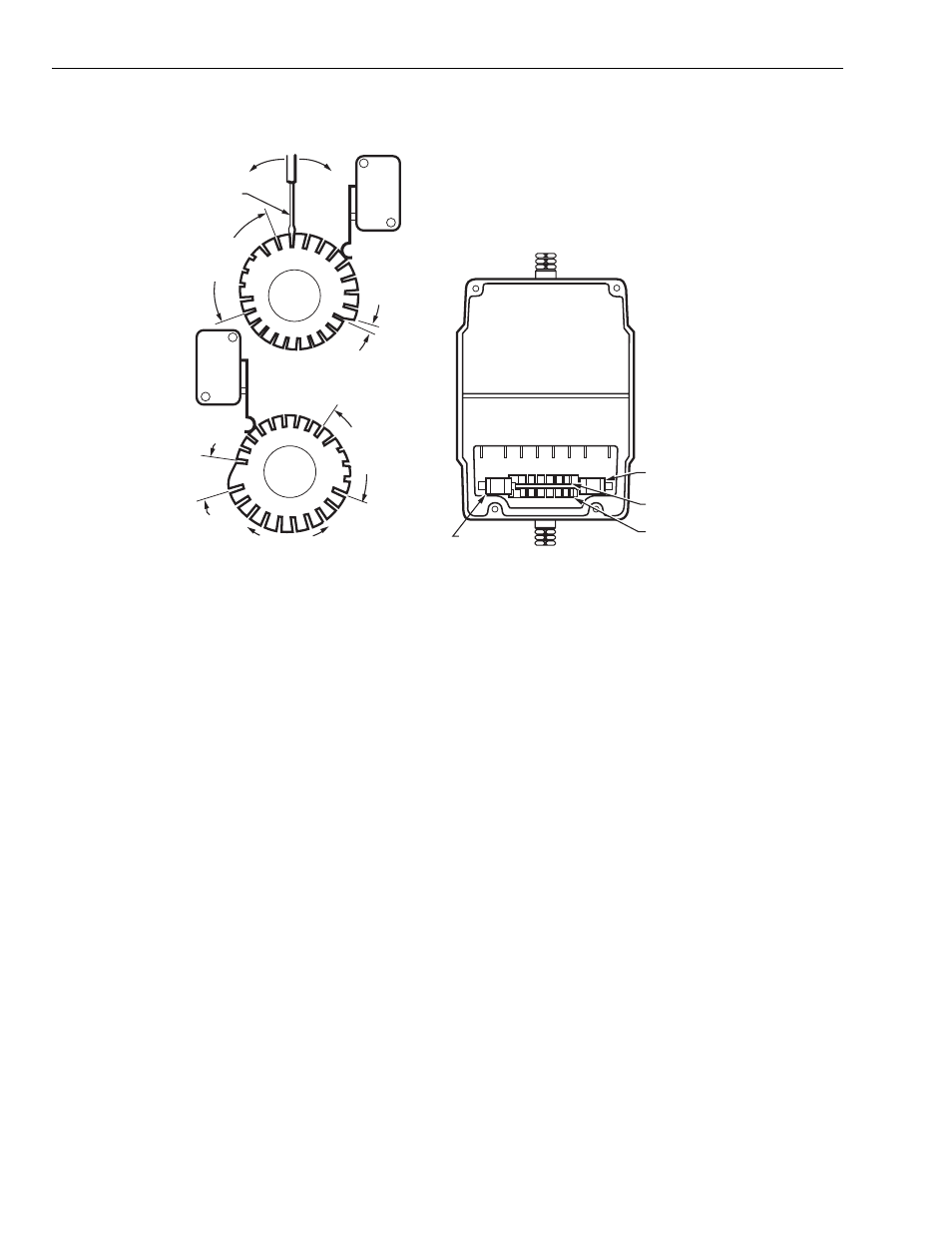
Fig. 13. Auxiliary switch adjustments.
OPERATION AND CHECKOUT
Operation
In an operational circuit, a single-pole, single-throw controller
or fan starter (line voltage for Series 41, or low voltage for
Series 81) is wired in series with the motor circuit. When the
controller switch closes, the motor is energized and runs to
the end of its stroke. At this point, the internal motor limit
switch opens, de-energizing the motor. The brake solenoid is
energized, however, and remains so as long as the controller
is closed. The brake holds the motor in the energized position
until the controller opens. At this point, the brake is released
and the spring returns it to the starting position.
Checkout
After the installation is complete, check the entire system for
the following points of operation:
• Motor operates the load properly.
• Motor responds properly to the controller.
• Motor returns to starting position when power is interrupted.
Damper Application
1. Check the entire motor-damper linkage to ensure that
the mechanical connections are secure and properly
made. Be certain the ball joint on the damper crank arm
is properly placed to give the required amount of travel.
2. Energize the motor and run it to the end of its stroke.
Check the damper linkage while the motor is running to
see that there are no loose or binding connections.
3. If the motor does not run, check the control circuit for an
open or short, the presence of power, and voltage at the
motor. Voltage at the motor must be at least 85 percent
of the rated voltage (specified on nameplate.) Ensure
that the maximum motor net load is not exceeded.
4. Interrupt the power to de-energize the motor and allow
the spring to return the motor to the starting position. If
the motor does not return, check to ensure that power is
actually interrupted and that the return load is not
exceeding the rated motor load.
RIGHT/INNER
AUXILIARY
SWITCH
FAST RISE
PORTION
(APPROX.
1 DIFF.)
SLOW RISE
PORTION
(APPROX.
10 DIFF.)
INNER
AUXILIARY
CAM
(BLUE)
NOTE: CAMS ARE OFFSET
VERTICALLY TO PROVIDE
BETTER VIEW OF BACK CAM.
FAST RISE
PORTION
(APPROX.
1 DIFF.)
SLOW RISE
PORTION
(APPROX.
10 DIFF.)
MOTOR
OPEN
MOTOR
CLOSE
POWER
END
OUTER
AUXILIARY
CAM
(RED)
LEFT/OUTER
AUXILIARY
SWITCH
M17101
POWER END
OF MOTOR
OUTER AUXILIARY
CAM (RED)
INNER AUXILIARY
CAM (BLUE)
RIGHT/INNER
AUXILIARY SWITCH
LEFT/OUTER
AUXILIARY
SWITCH
MOVE SCREWDRIVER AT
TOP ONLY TO ADJUST CAM.
1/8 INCH
STRAIGHT-BLADE
SCREWDRIVER